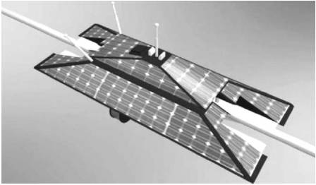
Figure 1. Model of a robot with Solar Panel
Managing overhead transmission assets-including towers, conductors, insulators and other components are costly and sometimes a dangerous proposition. Many lines are located in remote, rugged environments. Frequently, inspection workers conduct helicopter surveys and also climb towers. Some equipments cannot be inspected due to hazardous conditions or access restrictions. Robotics inspection system being developed by the authors promises to reduce costs, enhance safety, and expand coverage while improving reliability. This robot provides a real-time monitoring of physical threats or damage to electrical transmission line towers and conductors as well as provide operational parameters to transmission line operators to optimize transmission line operation. These transmission lines are located at remote area where monitoring was not able to provided. To rectify this problem, this robot has been designed and aims at enhancing the transmission system by minimizing its drawbacks like insulation damage, ageing, electrical outages (due to high risk trees) and ground clearance which are faced manually. By using automated system, human involvement can be minimized. In the proposed robot system, we can overcome all these problems. The data collected in this system can be transmitted to control room by providing the receiver and transmitter in each pole upto the end point. The communication between end point and control room takes place using existing infrastructure like cell or landline, internet or any other communication infrastructure. If line to ground monitoring is required, we can transmit and receive the data directly.
The power generating capacity of India is very low but the consumption rate is very high and the demand is also high. So we must use power efficiently and inorder to obtain efficient power transmission we can use robotic technology. The proposed robotic system consists of a current coil (insulation detector), infrared sensor, RC servomotors (it is an integral part of the robot), carbon composite frames, high definition camera, rotating shaft, vibration sensor, micro wheel, transmitter and receiver and monitoring device). Current coil is used to determine the flow of current through the live transmission lines and the variation in the current coil reading gives the quality of insulation. It is also used to determine the transmission voltage level. Infrared technology gives us the ability to “see” and measure temperatures on defective components and the normal wear, chemical contamination, corrosion, fatigue and faulty assembly in transmission system. Overheating can occur in virtually all electrical components and hardware including generators, transformers, pole top connections, insulators, disconnectors, jumpers, shoe connections, fuse connections, switchgear, starters, contactors and any other hardware one might imagine. In transmission and distribution systems, thermo graphic surveys can help cut production losses and prevent the eventual failure of these systems. Utilizing infrared thermography for electrical inspections can help to set maintenance priorities, prevent unplanned outages, reduce losses, reduce liability, evaluate repairs and maintain high performance. Infrared sensors also detect the ground clearance and wheels positions. RC servo motor is used for mechanical action of the robot. Without this motor the robot could not move in anyway and would only be able to perform stationary actions that require no movements. Carbon composite provides us high strength and less weight insulating frames. Solar panels provide power to the robot for operation by converting the solar energy into electrical energy. Vibration sensors are used to detect the hissing noise.High definition camera is used to view ageing problems and disturbance (trees) which cause electrical outages. In the rotating shaft, infrared red camera, high definition camera and electrical coil are mounted to monitor the entire cross sectional area of the live conductor. Micro wheels for the robot movement are fixed over the live conductors. Transmitter is used to transmit the information gathered by the robot and receiver is used to receive the information from transmitter. The power given to the robot can be in the form of solar as shown in Figure 1 by using the solar panel.
Figure 1. Model of a robot with Solar Panel
Transmission lines are exposed to variety of factors, such as corrosion and wind induced vibrations, which cause different problems and limit the life time of the lines. This damage can be classified as two main groups: Damage to the insulators and damage to the conductors.
The insulators are affected by impact of weathering, thermal loading, electro thermal causes, cement growth etc., Temperature difference between hot sunny days and freezing cold nights as well as the heat generated by fault current arcs causes thermal cycling, which produces micro cracks and allows water to penetrate into the material. Thus it causes damages to the insulators.
The steel reinforced aluminium conductors(ACSR) are one of the most popular conductor types. The most important phenomenon that degrades such conductors is corrosion of aluminium strands. Pollutants and moisture, in the form of aqueous solutions containing chloride ions, ingress into the interface between the steel and aluminium strands and attacks galvanizing protection of steel, which leads to galvanic corrosion between iron and aluminium. In addition to corrosion, wind induced vibration can cause severe damage to the mechanical system.
Damage in the line can be detected through investigation of their symptoms. Most of the line problems produce unusual partial discharges. Whenever the electric field intensity on the line surface exceeds the breakdown strength of the air, electrons in air around the conductor ionize the gas molecules, and partial discharges namely corona effect, occur. High frequency partial discharges produce radio noise in ultra-high frequency range. In addition to the noise, discharges send a current to the line. This current can also be used to detect faults. Depending upon the weather, age of the line, problem conditions and other factors, level of the discharge can also be different.
Robotic inspection involves the use of autonomous or remotely controlled machines that incorporate imaging, sensing and other technologies to assess the condition and status of transmission system components. The idea is to reduce or eliminate human exposure to potentially dangerous environments while collecting the data required for meeting stringent reliability standards on tight maintenance budgets. The autonomous transmission line inspection robot is intended to reduce or eliminate the need for helicopter over flights while supporting a transition from scheduled to condition-based maintenance on both existing and new corridors. The motors will run on power harvested from shield wires, supplemented by output from on-board solar panels. High definition cameras and other equipments will identify nearby trees that could pose a risk to wires, evaluate right-of- way encroachment, and assess component condition by comparing images taken from different locations and at different times. Simple electromagnetic interference detectors will identify discharge activity and other indicators of faulty equipment.
The heart of the system is the electronics package. It is located on high-voltage transmission line that may have a line to ground potential upto or even greater than 500 kV ac. The package is required to protect from weather and the effects of corona. The mounting enclosure provides these two requirements and must be vibration free and “hot stick” deployable to prevent de-energizing the transmission line when installing the sensor platform. The electronics packages with mounting enclosure is shown in Figure 2.
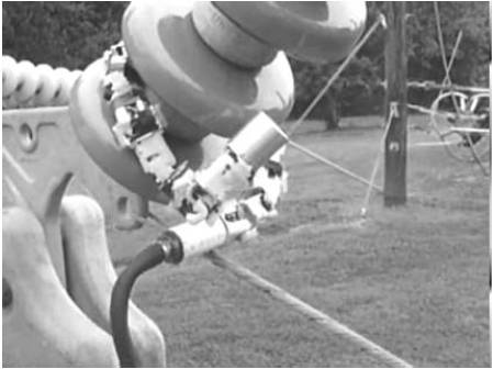
Figure 2. Mounting Enclosure
A two-axis accelerometer (vibration sensor) and two pass band filter provide the vibration detection interface to the sensor DSP. The vibration sensors are located on the circuit board and oriented such that vibrations in the plane of the board are measured relative to the axial direction of the transmission line conductors, Two pass band filters with gain are used to amplify the vibration signals and reject all out of band signals that are not considered to be caused by tower tampering. The resulting signals are delivered to the sensor DSP where the sensor time domain signals are converted to the frequency domain through the application of a Fast Fourier Transform (FFT).Once in the frequency domain, known vibrations not related to tampering can be effectively filtered out through simple addition and subtraction. Signals removed include those related to the transmission line 60-Hz fundamental and its harmonics. The resulting frequency spectra is then summed and compared to a threshold, and the valued that exceed the threshold are reported to the operator via the onboard radio link and the endpoint.
A pyro-electric infrared sensor with an infrared pass band from 4 to 12 microns, an IR lens and a pass band filter provide the motion detection interface to the sensor DSP. The IR sensor sensitivity is located in the human body's black body radiation range giving a warm object(human or animal) a high contrast against a warmer or colder background. The sensor responds to a change in radiation (dIR/dt) over a period of time within its pass band that detects movement as opposed to detecting the absolute level of IR radiation. This characteristic gives the sensor the ability to detect the movement in hot or cold or night or day conditions. A specially designed IR lens with a focal length of about 60 ft is used to focus an object the size of the human body as viewed from above and located at the base of the tower on the sensing elements. An electrical pass band filter with gain is used to amplify the low-level signal from the sensor and rejects changes in the output that are out of band with the expected movement of warm bodies at the base of the tower. The output of the sensor and lens is delivered to the DSP where further processing takes place to reject naturally occurring IR changes.
Each TLSM (Transmission Line Security Monitor) is intended to be mounted on a conductor close to the insulator holding it at each tower of a transmission line or a section of a transmission line. From this vantage point it can detect warm body movement at the base of each tower and vibration associated with that tower. When thresholds are exceeded, a message is generated and transmitted to the transmission line control room to alert operation that a possible threat to a tower is occurring. The distances between the operator and the alarming TLSM can be several hundred miles away as well as in areas where communication infrastructure does not exist. To implement communication, each TLSM contains an RF transmitter that is capable of acting as a network node in a one-dimensional network, transmitting information from each sensor to the operators. A custom designed antenna is used to transmit and receive electromagnetic radiation from each of the sensor platforms completing the communication link. The antenna is located in a slightly conductive dome further protecting the antenna and cabling from the high electric fields. The working of the robotic system can be explained with the help of Figure 3.
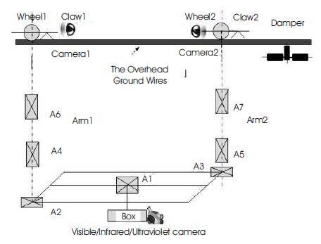
Figure 3. Working System
The endpoint performs a supporting role for the sensor platform in that it complets the link between the sensor platforms and the transmission line control room operators. Its function is to provide an information connection between the sensor platforms and existing communication infrastructure such as land line telephone, cell phone, internet, or any other means available to deliver information to the operators. Together the sensor platforms and at least one endpoint make up the TLSM. It is supported by two-way communication protocol, packet encoding and decoding , and short-term energy storage. It is intended to be located where information infrastructure exists such as the power generating end or the load end in a substation.
During the development of the robot, mechanical system able to move along a cable of a transmission line is needed. The methodology of development of the mechanical system includes the study of wind effects on the robot. Depending on the results, the configuration of the robot could be changed, since it is foreseen, and the visualization of the conducting cable, also. Then, some possible configuration is studied to implement the requirements and, finally the moving power is calculated, based on the robot mass forecast, and the pulleys of vehicle traction system. The various configuration of mechanical system of the robot is shown below in Figure 4.
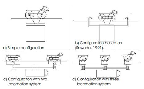
Figure 4. Mechanical Configuration of Robot
When the robot is placed on the transmission line, the main factor to be considered is wind effect because the level of the transmission line from the ground is very high so the speed of the wind is also high. It causes the robot to oscillate or it may fall from the transmission line. During the study of the wind effect on the robot, two hypotheses are considered: the robot is modeled as a simple pendulum or as two opposing pendulums. The results pointed here are qualitative, but lead to conclusions about the influence of the shape and configuration in the reduction of the amplitude of oscillation and in the improvement of the stability of the system.
The model of simple pendulum is shown in Figure 5, serving as comparison with the model of opposing pendulums, emphasizing the level of interference of the form on the oscillations. For this reason, cylindrical and parallelepipedical forms for the robot were studied.
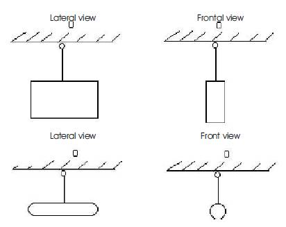
Figure 5. Simple Pendulum Model
From the above study, the authors concluded that
A configuration that diminishes the amplitude of oscillation of the robot due to the effect of the wind is two cylinders, one above and other below the cable. In this case, preserving the input data of previous models allowed a qualitative comparison, and is shown in Figure 6.
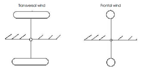
Figure 6. Opposing Pendulum Model
From the above study, they conclude that,
An aging asset base, stringent vegetation management and reliability requirements, and continuing budget pressures increase the need for thorough, timely, and cost-effective monitoring and condition-based maintenance along the entire length of transmission lines. Robotic inspection promises to deliver actionable condition assessment data and information from environments that cannot be readily accessed today, as well as to improve worker safety.
In this paper, a robot for the inspection of transmission lines was developed, decreasing the time interval of line disconnection and increasing the safety of maintenance procedures. This mobile robot can be used as basis for future developments, generating a more complete system for energy transmission line services. Among future developments, the implementation of a tool to be placed to remove aircraft warning spheres is foreseen, as well as tools to carry out repair in damaged cables; and, finally, a system to execute autonomous inspection through the recognition of damages in the ground cables.