
Figure 1. Water Flow Meter
As technology changes, automation plays an important role in handling the systems. After the invention of the wheel, various types of vehicles were introduced. The internal combustion engines run on liquid fuel, which should be very efficient from the economic point of view as day-by-day, the fuel becomes very expensive. For proper indication of the fuel, the entire vehicle has a smart fuel indication system, which is inbuilt into the vehicles. Without this smart fuel indicator, the oil distributor trying to cheat while filling the fuel tank at the fuel station. In this paper, the authors proposed a method by which we can continuously monitor the fuel level of the vehicle before filling the fuel and after filling the fuel.
In today's world, automation is the basic requirement for handling all the systems, which has become possible because of an embedded system. The embedded system is a combination of hardware as well as software, often with the real-time calculation constraints (Nagaraja et al., 2009). It is also important from the accuracy point of view that automation also reduces the probability of error which mostly occurs due to human mistakes. It also optimizes the result by reducing the size and the product cost, thus improving the reliability and performance (Dalci et al., 2004). The transportation system is mostly affected by causes, such as fuel theft, fuel leakage, and improper fuel consumption in the engine and mostly with the disputes that occur while refueling the vehicle. This issue causes a drastic change or loss in the fuel level, which can create a great trouble for the authority since fuel theft creates a major problem for the owners and the drivers (Meribout et al., 2004). In this paper, a systematic approach will tend to reduce the fuel theft activities in an effective way. Equipments which run on fuel, such as cars, motorcycles, bus, trucks, generators, and compressors are to be powered by an internal combustion engine so that these can run efficiently for a long time as possible. Almost every equipment has a fuel level meter in terms of analog meter, which does not clearly indicate the level of fuel. So it is very important for us to design a device which can clearly indicate the fuel level before and after filling the tank at the fuel station (Raja and Geetha, 2016). The major problem with the equipment is to know the level of the tank, how much fuel is left in the tank, and about the safety, security, and benefits (Aher and Kokate, 2012; Vijayaraghavan and Raj, 2013). The safety and security of fuel are important for the demands of oil and costs of fuel increasing day by day. This indirectly increases the overheads of the many businessmen whose whole business depends upon heavy vehicles. However, it is a time of rapid change of market and it is forecasting has become most difficult (Huang et al., 2010). In addition to this, due to increase in the cost of fuel, the theft activities have also increased, and also fuel leakage, dry, out of the fuel prematurely, the problem of inaccurate refilling of the tank, improper consumption of fuel by the engine and also due to driver's misbehavior (Wable and Shinde, 2016; Kolhare and Thorat, 2013). In this proposed work, it includes the design and implementation of the real-time fuel monitoring system (Aher and Kokate, 2012). An enhanced feature can also be added in future by entering the current price of fuel manually using keypad buttons. So the calculated price, according to the amount of fuel inlet would also be displayed on the Liquid Crystal Display (LCD) (Dhande et al., 2014). The real-time fuel monitoring system will definitely ensure the inlet amount of the fuel, reduce the operating cost, and also help in getting maximum profit. This system is user-friendly and also easy to install at a very low cost (Senthilraja et al., 2014).
In this paper, a method is proposed to determine the amount of fuel during the fuel inlet, so that the problems, such as fuel theft, fuel leakage, and mostly with the disputes occuring while refueling the vehicle could be handled. It helps in predicting the inaccurate refilling of the fuel tank. This technique will provide better solutions than the existing issues related to fuel theft.
Reza et al. (2010) have proposed a method for automated sensing and controlling of water flow via a microcontroller. In this method, a microcontroller gets input from the sensor, which senses the water level with the help of an inverter (Meribout et al., 2004). Hemnandan et al. (2011) have proposed and implemented a system to remotely monitor fuel level of a diesel generator set. On the requirement of fuel, a short message was sent to the M33 Global System for Mobile (GSM) module in a remote location and in order to detect the fuel status, an ultrasonic sensor is used, and to display, readings are done through LCD display and Light Emitting Diode (LED) bar graph. Then in terms of alarm, information is sent back to the module via GSM network (Reza et al., 2010). Aher and Kokate proposed a system based on the microprocessor to monitor fuel and track the vehicle. This system is placed inside a vehicle to continuously monitor the fuel level with the help of a reed switch and also tracks the vehicle continuously at different locations by using a Global Positioning System (GPS) device (Ramadan et al., 2012). Senthilraja et al. (2014) have proposed a method to detect fuel and fuel theft, and also to track vehicle’s position using a third party monitoring software. Whenever the fuel is stolen, the sensor senses the fuel level and stores the information in the database and based on the calculations by the third party monitoring software, it provides a notification (Hemnandan et al., 2011).
The fuel is being stolen during refueling of the vehicle tank. The tank is filled with an amount less than printed in the bill or meter.
The aim of this paper is to measure the amount of fuel at the time of refilling the tank of the vehicle. This kit is to be placed in the fuel tank and the filling pipe. This system will start working while filling the tank, i.e. when the fuel flows through the pipe. This flow will make the turbine wheel to rotate and hence magnetic flux will interface the hall sensor. The rate of the interface depends upon the speed of the fuel flow. So the hall effect sensor produces the pulse signal output and this pulse can be calculated as water volume. The output signal generated by the flow sensor is used to calculate the volume of the fuel with the help of the microcontroller and display in the LCD. The flow meter is shown in Figure 1.
Microcontroller saves the final data into the Source Digital (SD) Card in the form of an Excel sheet, which can be used to check the history of fueling later. The proposed flow chart is shown in Figure 2.
The block diagram of the proposed method is shown in Figure 3.
Figure 1. Water Flow Meter
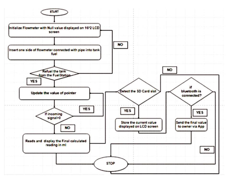
Figure 2. Flowchart of the Proposed Method
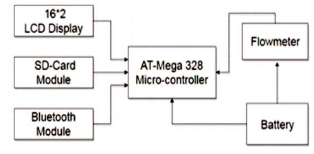
Figure 3. Block Diagram of the Proposed Method
The steps used in the proposed algorithm is given as follows.
1. First, configure the microcontroller and its pins.
2. Now, initialize main interface, Bluetooth, SD-card, LCD, and Flowmeter.
3. Check whether the Bluetooth is paired or not, if not paired then re-initialize it.
4. Continuously check the flowmeter data.
5. Run loop in program is repeated that keeps reading flowmeter data.
6. Display the changing values of petrol in liters on LCD 16 x 2.
7. Now, if flowmeter signals OFF, then it displays the calculated value on the LCD 16x2 display.
8. Send Short Message Service (SMS) via Bluetooth to the owner.
9. Save the calculated data on the SD card in the Excel sheet.
In the design of this model, various hardwares are used, such as flowmeter SD card, Bluetooth, etc. In this Installation, the device is placed in between fuel tank and the nozzle through which the fuel is to be filled. When there is no flow of fuel in the pipe, the device will remain OFF. Once the floor is detected by flowmeter, it will send the information via Bluetooth SD card so that the information about the volume of the fuel filled is determined.
Initially, in this design, the device is placed between the tank and the nozzle through which the tank is to be filled. The device is connected as shown in Figure 4. Along with the Bluetooth module, the SD card is also placed so that the actual reading of the level of fuel and the amount could be calculated. The device will also calculate the current volume of the fuel before filling the tank and once at the fuel station, once the fuel is filled the final reading or the information of the quantity after filling the tank is shown by the device. By this process, the user can easily know the exact volume of the petrol been filled by fuel filler. Once the device starts, the Bluetooth module senses the flow of fuel and sends the information to the SD card so that in future it can be seen that when the fuel is to be refilled. When the device initializes its state before start refilling of the fuel is shown in Figure 5. When the refilling of the fuel is completed, the count is displayed in LCD as shown in Figure 6
Microcontroller and sensors are used to detect the fuel level, whereas in this method the authors use a Bluetooth module along with SD card so that information can be stored, which can be analyzed in the future. The information stored current status of the level or volume of the fuel.
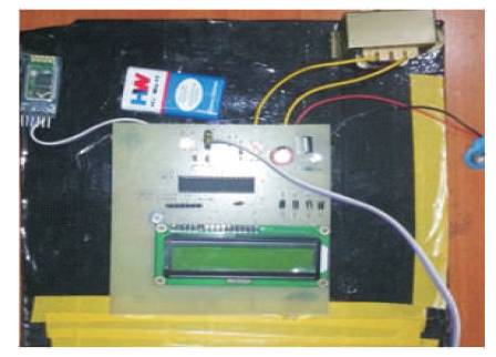
Figure 4. Hardware Connections
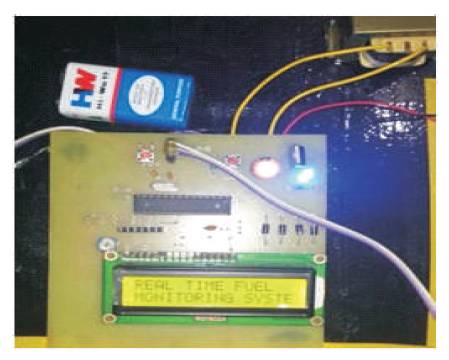
Figure 5. Initiation of Device before Refilling
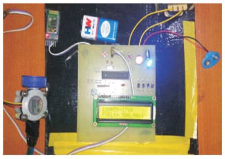
Figure 6. The Count after Refilling
This paper has been successfully implemented by a system that designing, can easily monitor the fuel level. The problem of monitoring fuel refilling at fuel stations has thus been resolved.
In this paper, the proposed work helps in predicting the inaccurate refilling of the fuel tank and also the improper fuel consumption in the vehicle. This technique will provide better solutions than the existing issues related to fuel theft. Whenever intrusion or tampering of fuel is done, the smart fuel detection system gets activated and the owner would know the precise indication of the vehicle and its fuel content. The basic purpose of this design is to provide security to the fuel tank. By this method, the standard of measurement system will improve because of the Digital Fuel Meter.
Expression of giving thanks are just a part of those feelings which are too large for words but shall remain as memories of wonderful people with whom we got the pleasure of working during the completion of this work and also grateful to Shri Shankaracharya Institute of Professional Management and Technology, Raipur which helped me to complete my work by giving encouraging environment. We would like to express our deep and sincere gratitude to our supervisors, Assistant Professor, Mr. Dharmendra Singh and Mrs. Hemlata Sinha. Their wide knowledge and logical way of thinking have been of great value to us. Their understanding, encouraging, and personal guidance have provided a good basis for the present work.