Figure 1. PV Cell Equivalent Circuit
Nowadays, the growth of Module Integrated Converters (MIC) concept is going on increasing. This concept was developed for Photovoltaic (PV) applications to improve the efficiency of the converters. In this paper, the authors have proposed a submodule Maximum Power Point (MPP) tracking algorithm to track the maximum power from the partially shaded cells. Generally, PV module have three submodules. Each submodule is formed by series connection of two strings. Here a different Perturb and Observe (P & O) algorithm is considered for each submodule to track maximum power from the all three submodules. Each submodule will have their own DC-DC converter. In Direct Current (DC) stage, DC-DC converters are connected in three configurations to serve sufficient energy to inverter for single phase grid connected systems.
Grid connected PV systems have several PV modules and one or more PV converters. These systems can be realized in different ways and this concept can be distinguished (Kjaer et al., 2005) from Centralized converters, string-and multistring converter, PV module integrated DC-DC converter, and AC modules.
Module Integrated Converters (MICs) for PV system have been developing very rapidly in recent years. The MICs are used to track maximum power point tracking on each module, permit the modules in series string to operate at different optimum voltage and currents, thus increasing energy capture by more than 30% during partial shadings (Burger et al., 2010; Oldenkamp and de Jong, 2009; Kasper et al., 2014).
However, there is usually mismatch between the series connected cells, which is typically the results of partial shading, manufacturing variations, and temperature variations. Since all the cells (or) modules connected in series string share the same current (Araújo et al., 2010; Attanasio et al., 2012; Baliga et al., 2010). The output power may be restricted cells (or) modules. A bypass diode is connected in parallel to the module to attenuate this mismatch and present PV hot spotting, but still the efficiency loss is noteworthy only when a central converter is used to track MPP on the PV string.
A distributed algorithm that works on submodule level gives true MPPT. This algorithm works on Differential Power Processing (DPP) (Bell and Pilawa-Podgurski, 2015; Qin et al., 2014) architecture which works on providing the series PV string with the mismatched current. DPP architecture helps in reducing the size of the overall PV system, cost and also increases the power conversion efficiency (Pilawa-Podgurski and Perreault, 2013; Qin et al., 2014). The two extremely dominant architectures are Micro Inverter (Kjaer et al., 2005; Oldenkamp and de Jong, 2009) shown in Figure 3(b), and DC optimizers (Burger et al., 2010; Li and Wolfs, 2008) shown in Figures 4 and 5.
The major constraints of these two solutions are the distributed converters are connected in series with the PV modules and must process the full power output of energy module.
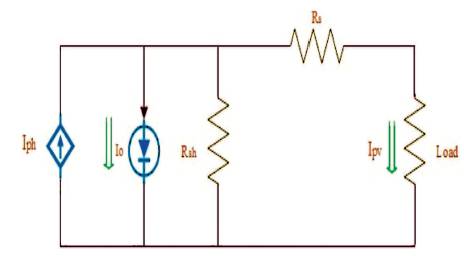
A solar cell is basically a p-n junction fabricated in a thin wafer of semiconductor. The electromagnetic radiation of solar energy can be directly converted to electricity through photovoltaic effect (Bletterie et al., 2008; Cao et al., 2008; Chapman et al., 2010). Being exposed to the sunlight, photons with energy greater than the band-gap energy of the semiconductor creates some electron-hole pairs proportional to the incident irradiation (Esram et al., 2007; U.S. Patent No. 7,796,412 (2010); U.S. Patent No. 8,035,257B2 (2011)). The PV cell equivalent circuit is shown in Figure 1.
The current source I represents the cell photocurrent. R and R are the intrinsic shunt and series resistances of the s cell, respectively. Usually the value of R is very large and that of R is very small, hence they may be neglected to simplify the analysis. PV cells are grouped in larger units called PV module which are further interconnected in a parallel-series configuration to form PV arrays (Pandiarajan and Muthu, 2011).
Vpv is output voltage of a PV module (V)
Ipv is output current of a PV module (A)
Tr is the reference temperature = 298 K
T is the module operating temperature in Kelvin
Iph is the light generated current in a PV module (A)
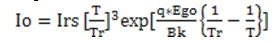
I0 is the PV module saturation current (A)
A = B is an ideality factor = 1.6
k is Boltzman constant = 1.3805 × 10⁻²³ J/K
q is Electron charge = 1.6 × 10⁻¹⁹ C
Rs is the series resistance of a PV module
Iscr is the PV module short-circuit current at 25oC and 1000 W/m2 = 2.55A
Ki is the short-circuit current temperature co-efficient at
Iscr = 0.0017A / oC
λ=PV module illumination (W/m2 ) = 1000 W/m2
Ego is the band gap for silicon = 1.1 eV
Ns is the number of cells connected in series
Np is the number of cells connected in parallel
Figure 1. PV Cell Equivalent Circuit
The Photovoltaic module can be modelled mathematically as given in equations shown in below.
Photovoltaic cell models have long been a source for the description of photovoltaic cell behaviors for researchers and professionals. The most common model used to predict energy production in photovoltaic cell modeling is the single diode circuit model. The ideal photovoltaic module consists of a single diode connected in parallel with a light generated current source (Isc).
The equation for the output current is given by

where
Photocurrent:

Module reverse saturation current:
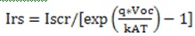
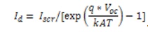
Module saturation current:
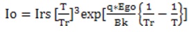
Module output current:
MPPT is done to obtain maximum power output from the PV module at a given irradiation and temperature condition. In applications where load needs more power than produced by the PV module, power converters can be used to increase the output as required (MacAlpine et al., 2013; Pragallapati and Agarwal, 2013). There are many approaches to get the maximum output using MPPT and the choice of MPPT depends on various factors, which include implementation complexity, cost, response time, ability to detect local and global MPP, etc. In case of uniform insolation, there is only a single MPP and conventional techniques, include Perturb and Observe (P & O), hill climbing, and Incremental conductance (Jehle, 2013; Carbone, 2015).
When some cells or sub-module comes under partial shading then these conventional techniques to maximize power are not very effective due to multiple peaks created in the P-V characteristics. These peaks are formed due to the bypass diode used to prevent hot spot and these local maxima are mistaken for global maxima by these techniques. Effective MPPT technique must be used to obtain global peak power and utilize the modules to best of their efficiency. Here in this paper, (P&O) algorithm is used to maximize the current and voltage individually in separate loops and with the help of this information, DPP converter are used to run the main algorithm which will seek true MPPT (Du and Lu, 2011; Brekken et al., 2002).
P&O technique and hill climbing method have gathered much focus among all the conventional MPPT techniques. Fundamentally both methods are same, but are approached from a different way. The operating voltage is perturbed in case of P&O method and in case of hill climbing technique, duty ratio perturbation is done which in turn will change the PV array current and thus array voltage (31MacAlpine et al., 2013). From the PV curve it can be seen that when the voltage is below Maximum Power Point Voltage (VMPP) and is increased (decreased), the power also increases (decreases) and in case the operating voltage is to the right of VMPP then increasing the voltage decreases the power and viceversa. So according to this P&O technique, if the power is increasing, then the perturbation direction should be same as before, but if the power decreases, direction of perturbation should be reversed. This process should be repeated till maximum power is obtained. Flow chart for MPPT technique using P&O is shown in Figure 2.
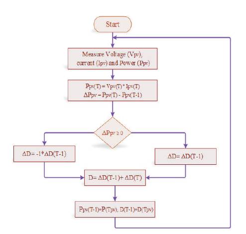
Figure 2. P&O MPPT
In this type, a DC-DC converter is called DC optimizer and are connected in series and each DC optimizer is operated at individual MPPT (Pragallapati and Agarwal, 2013; Bergveld et al., 2013; Meneses et al., 2013). The advantage with these converters are tracing the Maximum Power from the PV submodules individually and controlling them locally. Series connected Flyback DCDC converter are shown in Figure 3 (a) (Kasper et al., 2014; U.S. Patent No. 8,873,252 (2014)). This is done by connecting optimizers to each module which results in PV module that are independent of the system complexity. This system is intelligent, low cost, and reliable (Hu et al., 2013; Kadri et al., 2012; Kasper et al., 2013). These converters are operating in three modes, such as Buck, Boost, and Buck-Boost. The output of the converters is directly connected to the input of central inverter. By using the MICs (Dick, 2010), the string voltage is regulated to fixed value and this will enable low cost. MIC systems have an advantage that PV modules are decoupled from each other and the string can be operated at their own MPPT and are unaffected from variation in string current.
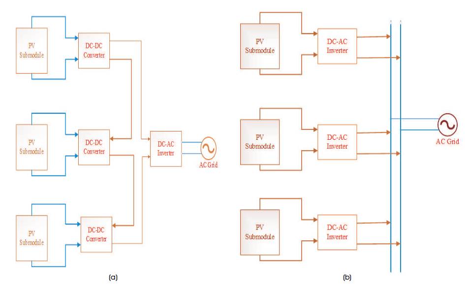
Figure 3. Two Types of Distributed Power Electronics Solutions for PV Systems, (a) DC Optimizer, (b) Microinverter
DPP maximizes energy capture from PV elements, which can be selected at the string level, panel level, or even cell level, while processing electrical energy just once (Qin et al., 2014; Stauth et al., 2012; Shenoy et al., 2012). The method employs modest low-power converters to handle only power mismatches. Bulk energy still flows through a series connection for delivery to a large inverter. The operation, control, and protection need of the inverter are simplified, yielding improved system performance-cost ratios.
The method follows, in part, from prior works by Shenoy et al. (2012) and Shimizu et al. (2001). Walker and Sernia (2004) have introduced an architecture in which DC-DC converters in parallel with the PV elements processes local power to enhance production (Krein et al., 2009; Krein et al., 2012; Krishnaswami et al., 2011). However, these converters process 100% of the PV power and must be rated at the PV panel's power. The advantages of DPP are that there is only one conversion step for bulk power, the converters are designed for reduced power ratings, and each PV element can be simultaneously optimized for maximum power production.
Figure 4 shows DPP architecture with converters connected to adjacent PV elements. Differential converters are implemented using DC-DC converters similar to battery balancing technology (U.S. Patent No. 5,479,083 (1995)) in this case. These DC-DC converters regulate PV voltage and current such that each operates at its maximum power point. In an ideal matched system, the local converters process no power and generates no loss. In a more typical well-matched system, the local converters handle only a small percentage of the power, while bulk power is sent directly to the large inverter (Kjaer, 2005; Stauth et al., 2012).
DPP architecture with converters connected to the main bus is shown in Figure 4. Various DC-DC converter topologies can be used to interface series PV elements to a collective bus. This bus may be the main bus, as depicted in Figure 4, an independent energy storage element, or a secondary bus. Under certain conditions, the power processed by the differential converters can be minimized to reduce power loss. The downside of this approach is that converter bus-side components have to be rated for the full bus voltage.
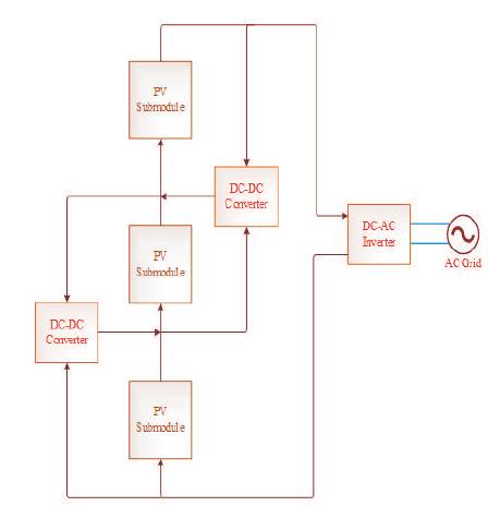
Figure 4. Differential Power Processing using DC-DC Converters Connected to Neighboring PV Elements
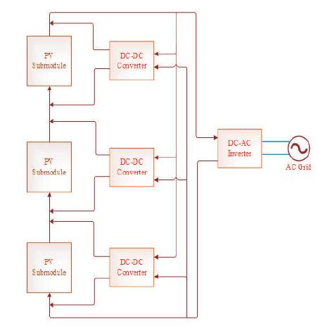
Figure 5. Differential Power Processing using DC-DC Converters Connected to Main Bus
In a typical installation, modules have a nominal energy performance spread of at least 3% across their ratings. Although many module manufacturers provide compensating ratings (e.g., 0% +3%), in principle more power is available on average. Here the operation will be adjusted to a target value under Standard Test Conditions (STC), with a distribution width of 3%, i.e. nominal ±1.5%.
Even in well-designed large installations, issues such as mounting and temperature variation introduce about another 2% spread. A conventional series connection delivers energy based on the lowest performer, producing about 3.5% than the potential energy delivery. With module-level maximum power tracking that is implementable with microinverters, power optimizers, or differential converters, there is no power reduction due to mismatch and the module output is higher on average
. For a DPP system, the full power of the PV array can be achieved, just as with microinverters or power optimizers. The DPP converters constitute an intermediate power processing stage with low ratings. For comparison, let the DPP converters be low-cost devices with efficiency of only 90%. In this example, a typical DPP converter processes about 3.5% of the total power. With an efficiency of 90%, the resulting conversion loss is less than 0.35%.
The central inverter can be customized, just as with power optimizers, and an efficiency of 99% is ultimately plausible. The total production is 98.65% of the adjusted panel ratings-higher than any of the other configurations, even though relatively inefficient low-cost converters are applied.
A key contrast in Table 1 is that in all methods except DPP, the losses stack up and the system efficiency is the product of multiple values. In the differential approach, bulk power is processed only once, and the impact on system loss is small. Modest cheap converters are wellsuited to the task. A variety of Maximum Power Point Tracking (MPPT) algorithms can be implemented using local information (Yang et al., 2010). The MPPT algorithm generates a reference for the controller compensator. The compensator in turn operates the local switches to maintain the converter at the given reference.
Table 1 shows an example situation based on a 100-kW scale installation with no shading, manufacturing tolerance of ±1.5%, and a combined mismatch spread of 3.5%, neglecting losses in cables and connectors.
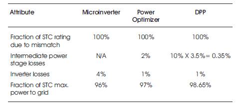
Table 1. Comparison of PV Power Processing Methods
The authors have worked in MATLAB/Simulink for the simulations. The simulation results for series connected flyback DC-DC converter is shown in Figure 6, for no mismatching current in PV submodule and Figure 7 shows mismatching currents in the PV submodule due to partial shadings on PV submodules. From Figure 6, the total powers processed by the DC optimizers and Central inverter are known. The output power is reduced below 300 Watts because of conversion losses present in the series connected flyback DC-DC converters with no partial shadings.
By observing the output waveforms of the inverter with partial shadings on submodules on the PV as shown in Figure 7, if anyone of the PV submodule is effected by partial shadings on it, the output power is reduced. By comparing waveforms Figures 6 and 7, it is clear that output power of the inverter is reduced due to partial shading. But this method is more advantageous compared to module integrated converters MICs.
he drawback of the series connected systems is eliminated by using the DPP system. This system drags the maximum power from the PV submodules when it is in partially shaded condition. Figure 8 shows the output power of the inverter with DPP systems without partial shadings. DPP converters are rated at lower than the PV submodule voltage and current ratings, so the losses present in this system are very low compared to DC optimizers. If there is no power difference on the series string, the DPP converters process zero power full power processed by the string to the inverter.
Figure 9 shows waveforms of the inverter with DPP architecture with partial shadings. By observing output waveforms of Figure 7 and Figure 9, the DPP system the power (in DPP power is more than 250 Watts) is improved compared to series connected flyback converters (in this method the power is 250 Watts). The DPP architecture also performs true MPP tracking and the output power is also improved
.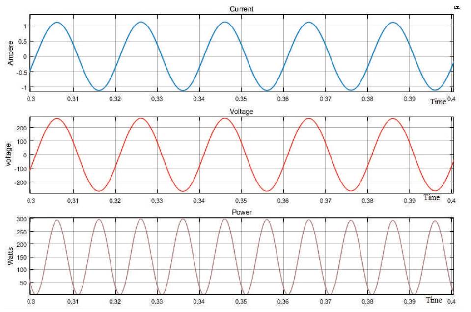
Figure 6. Series Connected Flyback DC-DC Converter without Partial Shading Effect
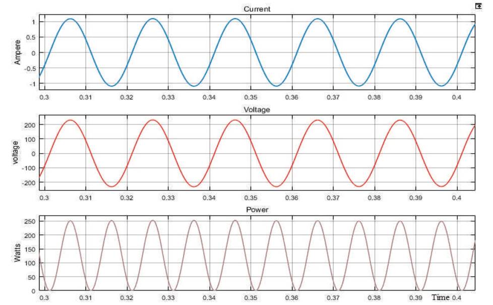
Figure 7. Series Connected Flyback DC-DC Converter with Partial Shading Effect
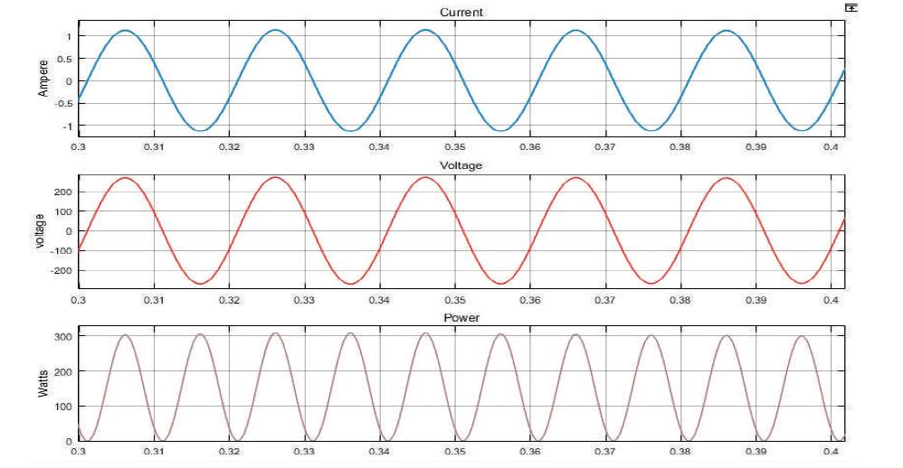
Figure 8. DPP Architecture with No Mismatching Current

Figure 9. DPP Architecture with Mismatching Current
In this paper, it is shown that the series connected flyback DC-DC converter has low efficiency and high cost compared to DPP systems. Series connected flyback converter system requires three DC-DC converters, where cost is increased due to number of converters usage and Switches rated at PV submodule level. It increases the switches’ cost and reduces the efficiency. In DPP architecture, PV-Virtual bus DPP system needs equal number of DC-DC converters as series connected submodules, and the switches rated at bus voltage and current ratings. Efficiency of the DC-DC converters have also improved. PV-PV DPP system with neighbor-toneighbor communication needs less numbers of DC-DC converters than the other systems and also the ratings of the switches are smaller than the submodule voltage and current ratings. The true MPP tracking is achieved from partially shaded PV cells and DC-DC converters.