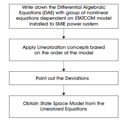
Figure 1. Flow Diagram of STATCOM System Description
In the context of power system, Static Synchronous Compensator (STATCOM) plays an important role to compensate stored energy in reactive elements. Lately, researchers are working for the selection of better optimized feedback Controller gains for the STATCOM control input. This paper presents a systematic approach for selecting such an optimized feedback control input, by considering the system with and without disturbances. Optimized control input models presented here is tested on the Single Machine Infinite Bus (SMIB) linearised Phillips-Heffron model of a power system installed with STATCOM using MATLAB/SIMULINK platform for damping oscillations.
As today’s power systems are much loaded compared to earlier days, increases to electro-mechanical oscillations all over the world (Haghshenas et al., 2016). These oscillations are in the range of 0.2 to 3 Hz. If these oscillations are not controlled, they will grow enormously in magnitude until loss of synchronize results (Kinariwala et al., 2015). In order to damp these developed oscillations and to increase system stability, incorporating Power System Stabilizer (PSS) is both inexpensive and effective. PSSs have been used for many years to control the developed oscillations in power system, but the PSS fails to control the great variations in the voltage profile and can even result in increasing of power factor and loss of system stability under severe disturbances. Recently, the community of power system has opened new opportunities for the application of the Flexible AC Transmission Systems (FACTS) as one of the most useful ways to improve power system operation controllability and solving various power system steady state control problems, such as voltage regulation, transfer capability enhancement, power flow control, and damping of power system oscillations. Lately, advancements in Static Reactive Compensation (STATCOM) technology based on Voltage Source Converter (VSC) concepts have produced significant benefits for the reactive power compensation. STATCOM systems offer rapid response to system events, improved voltage, power system stabilization, enhanced reliability, real and reactive power flow control, and increased power transfer limits. .
Reactive power increases with the reactive elements like indutor etc., available at the load sides. The increase in power factor results in the increase in power angle above 900 (system goes to unstable). Kinariwala et al. (2015) have analyzed the voltage sag and swells mitigation using STATCOM at distribution system. It has been observed that STATCOM is capable to control the PCC voltage at reference voltage with compensation of reactive power demanded by load. Rana and Aggarwal (2015) have been presented an model which can be used in order to analyze the Dynamic and the periodic steady state characteristics of the FACTS components.
The enhancement of damping the low frequency oscillations via tuning of static synchronous compensator (STATCOM) damping controller is investigated by Safari (2013). Lee and Sun (2002) have designed a STATCOM controller to damp the electromechanical oscillations in a power system. The results proved the effect of damping with this technique. In order to enhance both rotor angle and power system stability (Barati et al., 2010), the enhancement of damping power system oscillations via coordinated design of the Power System Stabilizer (PSS) and Static Synchronous Series Compensator (SSSC) and Static Synchronous Compensator (STATCOM) are investigated.
In view of all the above works, the researchers are working for the selection of best optimized feedback controller for damping oscillations in power system.
In the present work, selection of such an optimized feedback control for the STATCOM control input is designed by three different approaches of Linear Quadratic Regulator (LQR) and the results are compared to select best LQR in future. After, selecting such a best optimized feedback controller, the system is subjected to disturbaces and solved using Linear Quadratic Guassian (LQG) optimal control. The flow diagram of STATCOM shown in Figure 1.
Figure 1. Flow Diagram of STATCOM System Description
Figure 2 shows a single machine infinite bus power system connected with a STATCOM which consists of a Step-Down Transformer (SDT) with a leakage reactance XSDT , a three SDT phase GTO-based Voltage Source Converter (VSC) and a DC capacitor (Yadav et al., n.d; Shahgholian et al., 2008; Farahani et al., 2012).
The Non linear mode of the power system is,
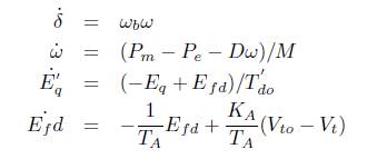
where,

By linearizing the above equations,
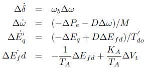
where,

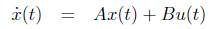
Its state space, formulation can be expressed as,
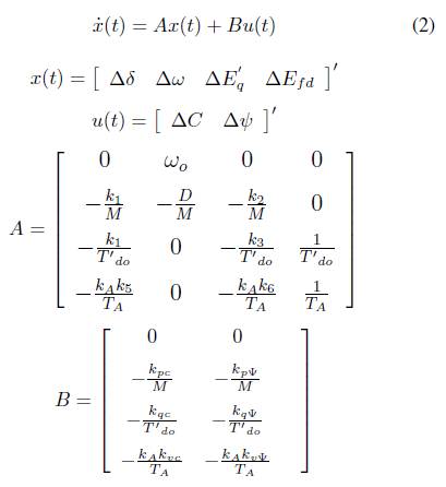
where, the state variables are the rotor angle deviation (∆δ), rotor speed deviation (∆ω), q-axis component deviation (∆E'q), and field voltage deviation (∆Efd).
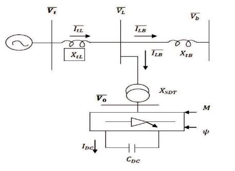
Figure 2. STATCOM Connected in a SMIB Power System
Optimal control theory, an extension of the calculus of variations, is a mathematical optimization method for deriving control policies. Optimal control allows us to directly formulate the performance objectives of control system for a given set of performance objectives. A control system which minimizes the cost associated with generating control inputs is called an optimal control system.
The LQR method determines the feedback gain matrix that minimizes performance index in order to achieve some compromise between the use of control effort and the response of the system that will guarantee a stable system (Yathisha and Kulkarni, 2013). Consider a system with
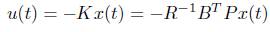
The input u is expressed as r - KX , where r is the reference input and K is the feedback gain, also called the control law. Now assume that the reference input r is zero and that the response of the system is excited by nonzero initial state x(0), which in turn excited by external disturbances. The problem is then to find a feedback gain to force the response to zero as quickly as possible. This is called the regulator problem. If r = 0, then the input u = -Kx and the closed loop system is given by,
The most systematic and popular method is to find K to minimize the quadratic performance index,
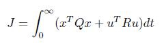
where Q and R are the positive-definite Hermitian or real symmetric matrix, respectively. From the above equations,
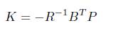
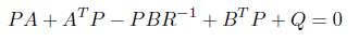
Therefore the control law is,
in which P must satisfy reduced Riccati equation:
The LQR function allows to choose two parameters, R and Q, which will balance the relative importance of the input and state in the cost function that is to be optimized. The weighting matrices Q =I and R =1 is chosen for the current research.
If a controller is designed using the LQR, and the observer is designed using Kalman filter, the resulting system is referred to as LQG Control or LQG compensator. In short the optimal compensator design is as follows (Yousef et al., 2008; Shaji and Ashwin, 2015):
Kalman filter is an optimal observer, which minimizes a statistical meausre of the estimation error, e0 = x- x0 , where is the estimated state vector. The state equation of the kalman filter can be written as:
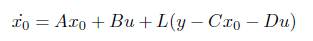
Since the Kalman filter is an optimal observer, the problem of Kalman filter is solved quite similarly to the optimal control problem. The algebraic riccatti equation is given by,

The algebraic riccati equation can be solved using the specified Kalman filter MATLAB command lqe (Linear Quadratic Estimator). The Kalman filter optimal gain L is given by,

where, L is the returned Kalman filter optimal gain, S is the returned solution to the algebraic riccatti equation, and E is a vector containing the eigenvalues of the Kalman filter (eigenvalues of A-LC).
The optimal LQR and LQG based controllers for the STATCOM control inputs with and without disturbances are experimented by considering the following scenarios.
For the two control inputs of STATCOM ∆C and ∆ψ, the optmized feedback controllers are designed using the LQR technique by tuning the weighting matrices with different approaches as shown below.
This rule was proposed by Oral et al. (2010).

This rule was proposed by Oral et al. (2010). Q = C'*C and R = B'*B
This technique was proposed by Pandey (2010) and is not simply selecting the Q & R matrices, it is a systematic way of designing LQR with different stages referred to as Multistage. The design procedure with different stages is as follows..
First Stage LQR: Using the Matlab command find the first stage LQR controller gain k from choosing the Q and R 1 weighting using Bryson rule.
[k , s, e] = lqr(A, B, Q, R)
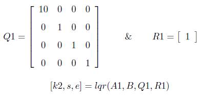
Second Stage LQR: A new state matrix A1 is obtained as A = A - (B * k1 ). With this knowledge find the second stage LQR controller, by changing the weighting matrices as,
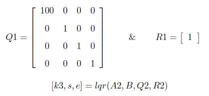
Third Stage LQR: A new another state matrix A2 is obtained as A2=A - (B * k2). With this knowledge find the third stage LQR controller by changing the weighting matrices as,
The experiments proposed with different LQRs (Scenario I) are conducted without any disturbances. If disturbance acts on the system, the LQG (LQR+kalman filter) control is proposed for the best LQR control selected from Scenario I to the control inputs of STATCOM ∆C and ∆ψ. To show this effectiveness of LQG control over LQR control under disturbance, the simulations are carried out by considering the process noise as W = 10*B'*B and measurement noise as V = 0.1*C*C'.
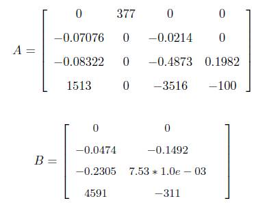
The experimental set-up to test the proposed algorithm consists of linearized Philips-Heffron model of SMIB described by matrices A and B below.
To, access the better LQR controller from three different approaches (Bryson, Bouderal, and Multisatge), the simulations are carried for the two control inputs of STATCOM ∆C and ∆ψ to the state variables ∆δ and ∆ω. The optimized feedback controller gains for the two controllers are as shown below,
K = [1.1660 -48.5170 0.6684 0.9781]
K = [0.0172 -8.6734 0.0190 0.0000]
K = [2.9657 -638.4131 9.6578 0.6493]
K = [14.2469 441.1895 -35.2721 -0.6082]
K = [0.0026 3.8337 -0.0074 -0.0000]
K = [20.6700 550.5130 -29.8065 -0.5705]
The dynamic response of all the state variables’ rotor angle deviation (∆δ), rotor speed deviation (∆ω), q-Axis component deviation (∆E'q), and field voltage deviation (∆Efd) with Bryson, Bouderal and Multistage LQRs approach are simulated for the STATCOM control inputs ∆C (Figures 4-7) and (Figures 8-11). Figures 12 and 13 show the response of rotor speed deviation with LQR and LQG for the two STATCOM control inputs ∆C and ∆ψ. Tables 1-4 show the comparison of peak overshoots (Mp) and Settling P time (Ts) for the STATCOM control inputs DC and Dy srespectively for all the four state variables. Performance analysis of (Mp,Ts and Steady state error ess ) for the optimal P controllers LQR and LQG, when the system is subjected to disturbances are shown in Tables 5 and 6 for the state variable deviation in rotor speed (∆ω).
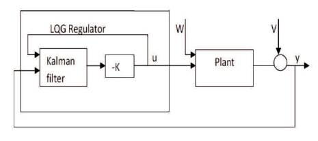
Figure 3. Block Diagram of Optimal LQG Compensator

Figure 4. Rotor Angle Deviation Response for ∆C
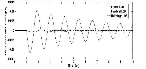
Figure 5. Rotor Speed Deviation Response for ∆C

Figure 6. q-Axis Component Deviation Response for ∆C
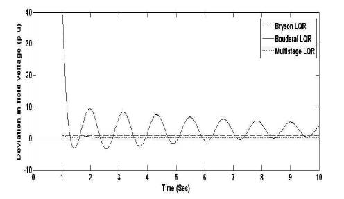
Figure 7. Field Voltage Deviation Response for ∆C
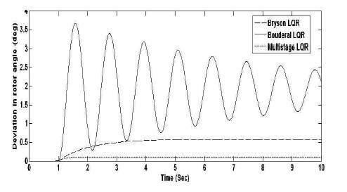
Figure 8. Rotor Angle Deviation Response for ∆ψ
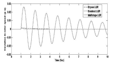
Figure 9. Rotor Speed Deviation Response for ∆ψ
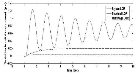
Figure 10. q-Axis Component Deviation Response for ∆ψ
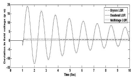
Figure 11. Field Voltage Deviation Response for ∆ψ
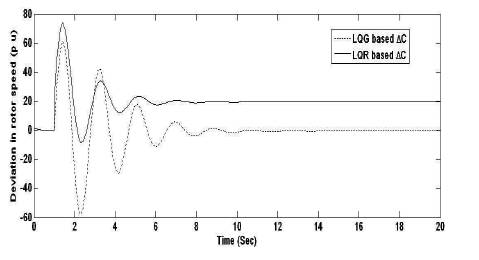
Figure 12. Rotor Speed Deviation Response for ∆C
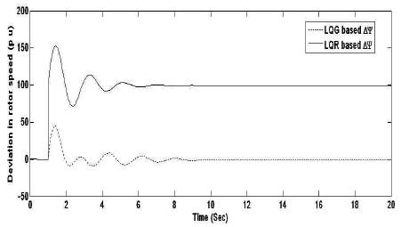
Figure 13. Rotor Speed Deviation Response ∆ψ
Figures 3 to 6 and Figures 7 to 10 show the simulation results of STATCOM control inputs ∆C and ∆ω with three different LQR approaches for the state variables ∆δ, ∆ω, ∆Eq' and ∆Efd , as mentioned in Scenario I. The comparison of two optimal controller (LQR and LQG) responses are shown in Figures 11 and 12 as stated in Scenario II. The comparison of peak overshoots (Mp) and settling time (Ts ) for Scenario I are tabulated in Tables 1 to 4. Tables 5 and 6 show the comparison of Mp , Ts and e for the two optimal feedback P controllers (LQR and LQG) when the disturbance acts on the system as mentioned in Scenario II.
Figures 3 to 6 and Tables 1 and 2 show the improved performance in multistage LQR based technique compared to other techniques (Bryson and Bouderal) for the STATCOM control input ∆C for all the state variables. For another STATCOM control input ∆ψ, the multistage LQR optimal control provides robust performance compared to all other approches of LQR for the state variables, ∆δ, ∆ω, ∆E'q . But for the state variable ∆Efd using Bryson LQR, the settling time is better compared to other LQRs.
From Scenario I, it reveals that the multistage LQR is the better optimal control compared to other techniques. According to Scenario II, the system is subjected to disturbance with multistage LQR approach. Figures 11 and 12 and Tables 5 and 6 (scenario II) conclude that when the system is subjected to disturbance, the LQG (LQR+kalman filter) control mimimizes peak overshoots and steady state error compared to conventional LQR control.
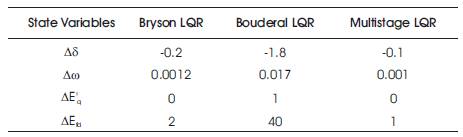
Table 1. Comparison of Mp for the STATCOM Control Input ∆C with Different LQR Approaches
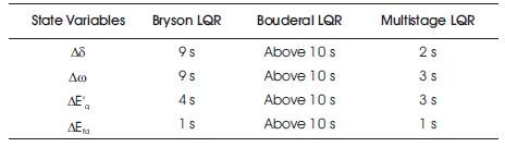
Table 2. Comparison of Ts for the STATCOM Control Input ∆C with Different LQR Approaches
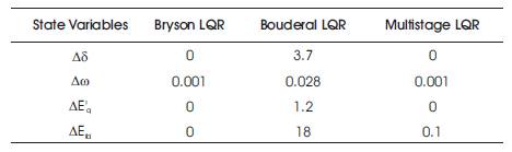
Table 3. Comparison of Mp for the STATCOM Control ∆ψ Input with Different LQR Approaches
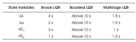
Table 4. Comparison of Ts for the STATCOM Control Input ∆ψ with Different LQR Approaches
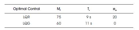
Table 5. Comparison of Mp , Ts and ess for ∆ω to the STATCOM Control Input ∆C
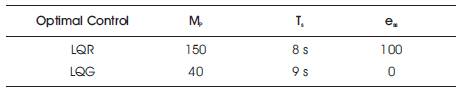
Table 6. Comparison of Mp, Ts, and ess for ∆ω to the STATCOM Control Input ∆ψ
The STATCOM is one of the most important shunt connected FACTS controllers to control the power flow and make better transients stability. A STATCOM is a controlled reactive power source. STATCOM has two control inputs (∆C, ∆ψ) for damping power system oscillations. Lately, researchers are working for the selection of best STATCOM control input by applying different advanced control techniques.
The power transfer limit is the maximum power that can be transferred in a power network between sources and loads without loss of synchronism. This approach has reduced the peak overshoot and settling time, which may inturn increase the power transfer capability. The other optimization methods for the STATCOM device are genetic algorithm, particle swarm optimization, etc. But the reason for choosing LQR method is that this approach is simple and easy to design, where other optimization techniques need more analysis and is time consuming. This paper provides application and comparison of two optimal controllers (LQR and LQG) for STATCOM in two stages. In the first stage (Scenario I), three different LQR approches are designed, applied and compared for both the control inputs of STATCOM. The results reveal that for both the STATCOM control inputs, the mutistage LQR approach provides better performance in all the state variables compared to Bryson and Bouderal LQR techniques. The multistage LQR based STATCOM control input ∆ψ provides robust performance for damping power system oscillations compared to other STATCOM control input ∆C.
In the second stage (Scenario II), the disturbances (state and process noises) are applied simultaneously after 1 second for better optimal control (multistage LQR from Scenario I) of the state variable ∆ω. The investigation reveals that the multistage LQR approach provides better performance when the system is not subjected to disturbance. When disturbance acts on the system, the multistage LQG (LQR+kalman filter) minimizes the peak overshoots, steady state error, and provides robust performance for damping power system oscillations compared to multistage LQR.
The authors wish to thank Dr. Syed Shakeeb Ur Rehman, Principal, Sree Jayachamarajendra College of Engineering, Mysore for his moral support and encouragement during this research work.