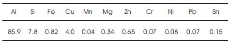
Table 1. Chemical Composition of the Work Material
The percentage of particulate SiC in the metal matrix was 10% by weight. Samples were fabricated in the form of cylindrical rods of 50 mm diameter and 175 mm length. The microstructure of the workpiece is shown in Figure 1. The tool holder used was PCLNR 25 25 M 12. The PCD inserts were of geometry CNMA 120408, which is one of the commonly used insert geometry for general turning application. The tool material was PCD 1500 medium grade. LMW CNC Lal-2 production lathe was used for the turning tests.
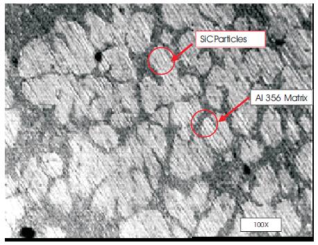
Figure 1. Microstructure of the Al SiC MMC
The machining of the fabricated composite was performed at three different cutting speeds of 200,300 & 400 m/min, in the CNC machine constant cutting speed command was invoked to ensure fixed cutting speed at varying work material diameter. Generally, AlSiC MMC machining with PCD inserts was observed to be more productive at higher cutting speeds. The cutting speeds were so chosen to reach the maximum cutting speed possible, for the given workpiece size. The feed rate was 0.075 mm/rev. The depth of cut used for machining was 0.50mm. All the tests were carried out under dry machining conditions.
The machining was interrupted at various time intervals and the surface roughness of the workpiece material and the flank wear land of the tool was measured. The surface roughness of the machined component was measured using a Mitutoyo Surf test 301 surface roughness tester. The Ra value of the surface roughness corresponding to each machining condition were measured. The worn insert tip was observed under the Mitutoyo TM 500 Toolmaker's microscope and the flank wear land was measured. Worn tool images are also presented
2. Results And Discussion
2.1 Tool wear
The main wear pattern physically observed on the cutting tool was the flank wear at the nose region. The flank face of the cutting tool also showed deep scratch marks parallel to the direction of the cutting speed. It was reported that at cutting speeds above 300 m/min the hard SiC particles grind the flank face of the cutting tool as if they are the abrasive particles of a grinding wheel [16]. The abrasive wear happening in the nose region of the PCD inserts. Two bodies and three body abrasive wear are also observed. Three-body abrasive wear is caused by the released hard particles, entrapped between the tool and the workpiece. [12]
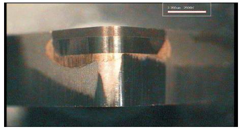
Figure 2. Flank portion of a Fresh Tool
Figure 2 depicts the nose region of a flank of a fresh tool. The nose region of the flank of the inserts after machining for 154, 48 and 27 minutes at cutting speeds 200, 300 and 400 m/min are shown in Figures 3, 4 and 5 respectively. The Figures 3, 4 & 5 clearly indicate substantial wear in the nose. The Figures also show vertical, parallel grooves, which were due to the hard SiC particles abrading the cutting tool [5].
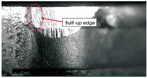
Figure 3. Flank Wear at V = 200m/min (After 154 min & Vb=0.4025 mm)
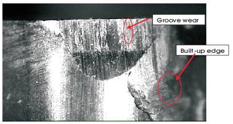
Figure 4. Flank Wear at V = 300m/min (After 48 min & Vb=0.415 mm)
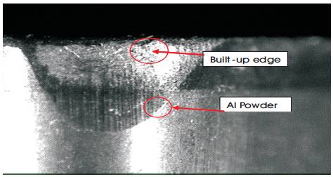
Figure 5. Flank Wear at V = 400m/min (After 27 min & Vb=0.445 mm)
2.2 Surface Finish
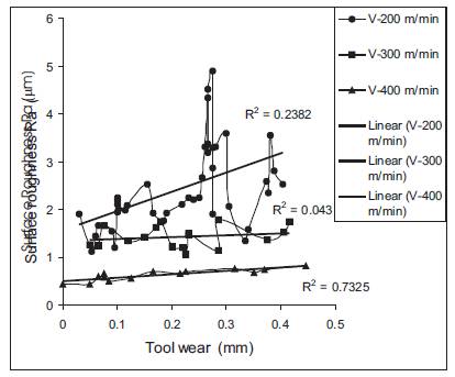
Figure 6. Surface Roughness (Ra) Versus Tool wear
Figure 6 shows the surface roughness (Ra) value, corresponding to various cutting speeds at various stages of tool wear. When cutting was carried out at 200 m/min, the surface roughness values in the graph show steep ups and downs. This is because of the formation of relatively stable BUE at this low cutting speed. This BUE prevents the nose region having contact with the work piece, leads to lees tool wear at lower cutting speeds [5].
Figure 6 also shows that the higher cutting speeds result in better surface finish. At higher cutting speeds removal of hard SiC particles from the Aluminum matrix becomes easier [6, 8]. The trend lines in the figure show that there is uniform increase in the surface roughness value in all the cutting speeds. This is a fact that, the surface roughness increases as the cutting tool wear increases. Due to the worn cutting edges, the tip of worn insert drags over the surface of the component and spoils the surface finish. In 400, and 300 m/min cutting speed, the trend lines are almost a straight line which show that, uniform surface finish is obtained or in other words at higher cutting speeds the influence of the tool wear on the surface finish is less pronounced. In 200 m/min the trend line shows the good inclination from the beginning of the tool wear to its end. It is clearly under stood that at low cutting speed the tool wear strongly influences the surface finish.
3. Artificial Neural Network Modeling
In the recent years the application of artificial intelligence is tremendous in virtually all fields of engineering. Modeling and optimization are necessary for the understanding and control of any process. Precise control is a prerequisite to achieve improved quality, and productivity.
Artificial Neural Network (ANN) plays an important role in predicting highly non-linear problems in different fields of engineering. Many researchers attempted to develop model from experimental data using statistical techniques. Out of this ANN model is performed well with less error and can be used for highly non-linear functions. Other modeling techniques like Finite Element Methods (FEM) and Response Surface Methodology (RSM) involve more mathematical equations and time consuming techniques .Hence ANN model is preferred in this work
In this study an ANN model has been constructed using the parameters cutting speed and time duration as input variables and Specific power consumption, tool flank wear and surface roughness as output variables. In this paper, however BPNN is chosen, since it provides several advantages over the other network and has been proven successful in different applications [17, 18]. The general architecture of a 2-9-2 network is selected for the problem, which is shown in Figure 7.
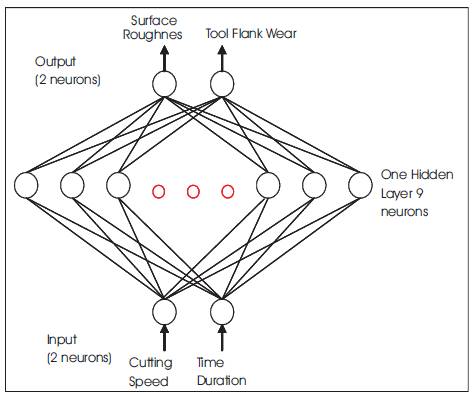
Figure 7. Configuration of the ANN model for Al SiC (10 p) MMC
This network uses back-propagation algorithm for training the network in an unsupervised manner. Table 2 shows typical observations of output response.
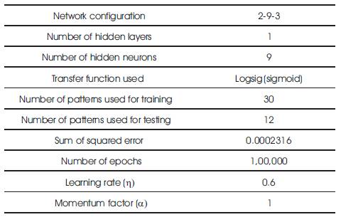
Table 2. Typical observations of output response
The transfer function used is log-sig. The network is trained by using 30 trials out of the 42 trails from experimental data and achieved the target RMS error of 0.0002316 by training the network up to 1,00,000 epochs. After the network has been successfully learned, then test the network by giving new set of input parameters and finding the out put parameters, thus by validating the data. Table 2 gives the typical observations of output response. Figure 8-9 show the Learning of ANN for conventional training for surface finish and tool wear respectively. Figures 10-11 show the validation of surface finish, and tool wears respectively.
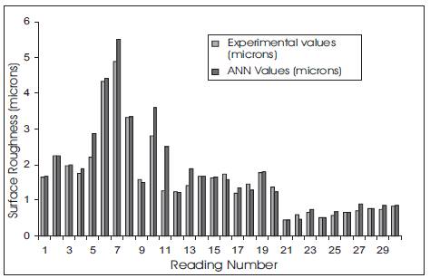
Figure 8. Learning of the ANN with conventional training for Surface finish of machining SiC(10p)
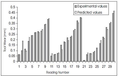
Figure 9. Learning of the ANN with conventional training for Tool Wear of machining SiC(10p)
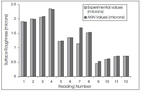
Figure 10. Validation of ANN model for Al-SiC (10p) machining for Surface Finish
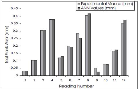
Figure 11. Validation of ANN model for Al-SiC (10p) machining for Tool Wear
Conclusion
- The primary wear mode is the wear in the nose region of the flank. The wear is believed due to the abrasive action of the SiC on the tool flank.
- Higher cutting speeds result easier removal of the hard SiC particles, resulting in better surface finish
- It is observed that, when machining at 200 m/min, tool life is near about 4.5 times more than the tool life of PCD machining at 400 m/min.
- The development of ANN model for predicting the parameters of Al/SiC 10p composites is to reduce the time and expenses involved in the experimentation to a great extent.
- The machining parameters of the Al/SiC (10p) composite can be represented with in a unified environment of the neural network. The knowledge is stored in a distributed fashion in the form of weights and thresholds of various neurons and connection links. This makes the ANN model more faults tolerant
- Once the ANN models captures the relation ship between the input variables and the machinability parameters of the composites during training, it is able to predict correctly the output values of the composites for the new set of input values outside the training set.
- It can be concluded that the Artificial Neural Network approach can be successfully employed to develop model for predicting the machinability parameters of Al/SiC (10p) composites The developed model predicted the outputs with in ± 15% error .