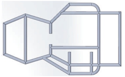
Figure 1. Chassis Design of Go-Kart
The aim of this paper is to reduce complexity in the overall design of Go- Kart to make it simple and light in weight without any premature failure and downfall in performance, since the efficiency of vehicles mainly depend upon the optimum design of its various elements. The Finite Element Analysis (FEM) method was used to create, evaluate, and recast the optimal Go-kart design to attain its objective. In addition to CAD software (SolidWorks and CATIA) were also used to design and analyse Go-Kart elements (chassis design, frame, composites, steering mechanism, braking system, and drive train design). So, finally an optimum proposal design would be prepared by considering its serviceability, safety, strength, cost, standardization, ergonomics, and aesthetics.
A Go-Kart is a single seater, four wheeler, high powered and small racing vehicle. Initially in 1956s, the motor based racing Go-Kart was developed in California by Artlngels (Capital Karts, 2016). In 1959, McColloch was the first company to produce engines for Go-Karts (The Evolution of Go-Karting, 2017). Immediately, rapid advancement in Go-Kart took place in other developing countries and presently it has a massive production in Europe (Fifty years of Karting, 1956-2006). Go-Kart is a selfpropelled vehicle whose speed varies from 45 kmph to 65 kmph (Raghuvanshi, Srivastav, & Mishra, 2015). At low speed, the battery ignition system produces better sparking. The Continuously Variable Transmission (CVT) is broadly classified into two categories: Torotrak and Van Doorne belt system, both of which have been the subject of much research and development work (Stone & Ball, 2004). The steering system provides directional control of the vehicle to the driver so that he is able to turn the vehicle in the required direction by changing the front wheel of the vehicle (Chu et al., 2012; Gao, Wang, & Wang, 2011). The main aspect of this research work is to analyze designs for safe and functional vehicle elements with a bit of innovation to achieve optimum design.
Designing is very essential to convert the less useful material to a more useful form because without designing, the production work becomes complicated. In a nutshell, the designing of product means preparation of drawing, specification, and developed work related to the product to be manufactured (Aulakh, 2016). The designing of any Go-Kart parts is a more risky work for every designer because unbeatable design requires high/deep thinking, and very precise calculation (Raghuvanshi et al., 2015).
The vehicle design includes the design and analysis of chassis, frame and braking system, etc.
Chassis is the major machine portion having all the parts required for efficient operation of the Go-Kart vehicle. The portion of a Go-Kart without body is known as chassis (Aulakh, 2013). The chassis comprises of the following main units like frame, brakes, power unit, electrical system, the steering system, suspension system, front and rear axles, etc. (Gupta, 2014). A good chassis design keeps the driver safe from impulsive forces and atmospheric temperatures. The material used for chassis design and its joint is made up of mild steel (Raghuvanshi et al., 2015). For the design of chassis, AISI-1018 material is widely used because it is easy to join, has the ability to resist externally applied forces without breaking, and is relatively soft (Faieza, Sapuan, Ariffin, Baharudin, & Supeni, 2004). The use of high strength material in Go-Kart is very much essential because the chassis prevent the parts to deform at the time of impulsive forces. In addition to AISI-1018, steel material is suitable for the chassis parts because it possesses a better mechanical and structural property, which helps in maintaining a low weight to strength ratio. This also helps in reducing weight. The chassis design and bottom view of Go-kart chassis is shown in Figures 1 and 2.
Figure 1. Chassis Design of Go-Kart
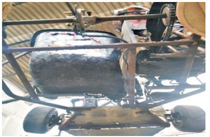
Figure 2. Bottom View of Go-Kart Chassis
A pipe having one inch diameter is more suitable for the manufacturing of chassis. The physical characteristics of material that help in the selection of manufacturing chassis components are reported in Table 1.
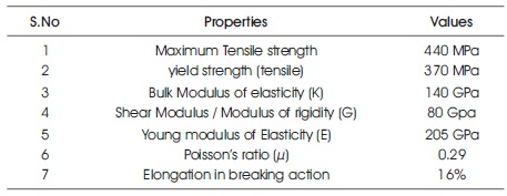
Table 1. Physical Properties of the Chassis Material (Kalita, Teja, & Manikanta, 2018)
The chemical composition of the Go-Kart material is depicted in Table 2.
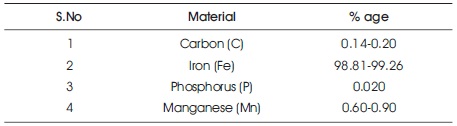
Table 2. The Chemical Composition (%age) of the Chassis Material (Taban, Gould, & Lippold, 2010)
Structural parameters of the chassis were tested by comparison of (AISI) standard values and the results are analyzed. The theoretically determined forces were carried out on the wireframe model of chassis frame at particular points to simulate the magnitude of the forces that the vehicle would experience due to its own weight during collision. By the use of finite element analysis, analysis was conducted. Subsequently, the existing design of the chassis was uploaded from the computer in order to conduct the Finite Element Analysis (FEA) of the chassis. Then stresses were determined from induced loads namely the frontal impact, side impact, and rear impact load.
As per the European New Car Assessment Program (ENCAP), in case of frontal impact the linear velocity remains at 64 km/h during pure elastic collision. Hence, using mass moment, impulsive forces were calculated by using the equation F = P×ΔT, (F= Impulsive force, P= Moment of the vehicles, ΔT =duration of time), normally the collision occurs is impulsive in nature. The collision time assumed to be,
ΔT = 1.020 in seconds and the kart's gross weight was observed to be 140 kg approximately
Therefore the moment of the vehicle at normal velocity (17.8 m/s or 64 kmph) can be calculated by using P = M × V,
P=Moment of the vehicle.
M= Mass of the vehicle.
V= velocity in m/s during impact.
Thus, P = 140 × 17.8, P =2492 kgm/s.
Now, the frontal impact force F = P × ΔT, F = 2492 × 1.020, F = 2741.2 N. After using the determined forces on the frontal part of the chassis frame and by fixing the rear part, the results generated by the software is shown in Figure 3.
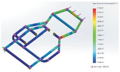
Figure 3. Front Side Chassis Analysis
In side impact situation, the impact forces were calculated same as in case of frontal impact despite of values which are different and was taken for calculation as mentioned. For the side impact kart, the normal velocity was taken to be 48.10 kmph or 13.30m/s in accordance to ENCAP Standard. Hence the forces calculated are- F = P × ΔT
Also, P = M × V, (moment of vehicle=mass× velocity)
P = 140 × 13.3, P = 1862 kgm/s.
Hence, the side impact force will be determined by using the formula (Force =moment of vehicles × time duration).
So, F = 1862 × 1.020,
F = 1899.24 N.
Therefore, the determined forces were used on one side of the chassis frame by fixing the opposite side and the stresses were simulated in software as represented in Figure 4.
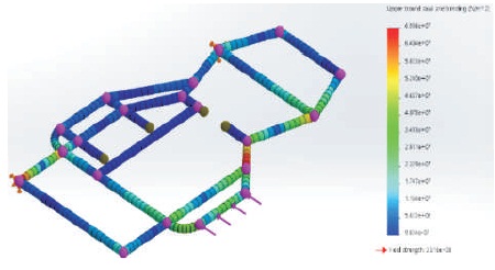
Figure 4. Analysis of the Sides
The force calculated during impact at rear portion were also determined same as the above cases. The normal velocity of collisions for rear side impact analysis is found to be 50 kmph or 13.8 m/s according to ENCAP standards. Calculations of force are as follows.
P = M × V
P = 140× 13.8, P = 1932 kgm/s.
Hence the rear impact force,
F = P× ΔT, F = 1932 × 1.02, F = 1970.64 N.
Then, the determined value of the rear impact force was applied on the rear part of the frame while fixing the frontal part. The image of rear side chassis analysis is depicted in Figure 5 and the analysis results are depicted in Table 3.
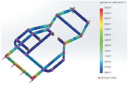
Figure 5. Rear Side Chassis Analysis
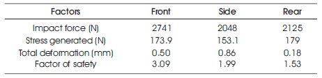
Table 3. Technically Calculated Values of the Rear Impact Force
The values from the above mentioned analysis are accurate. They ensure the full safety of the design. However, these loading conditions do not represent exact conditions of actual impact. To study typical collisions and impacts accurately, parameters like dynamic loading would have to be accomplished. These collision forces which will be generated in a real crash of the kart are studied and simulated. It becomes quite hard to simulate and examine this action accurately without collecting known data from a real crash in different positions. This data could be traced with the help of transducers like strain gauges, which can be attached to the outbreaks of chassis of the kart. Data collected from the simulations show that the chassis of the vehicle tends to have a factor of safety 2.0. The magnitude of factor of the safety shows that chassis of vehicle ensures safety of driver to the fullest. By mounting the seat belts with one of the most rigid frame members, it ensures safety and stability of seat belt under the effect of maximum forces that would possibly be generated in the collision. Quick release lever style seat belt clasp can be also used to provide safety to the driver and for escaping driver in less time. The safety members integrated in the kart will be enough to face and tolerate all the impacts and will keep the driver safe during collision.
The purpose of Go-Kart frame design is to withstand the accidental impacts, direct loads, and stresses due to breaking and provide rigid support for mounting each part of the Go-Kart (Khilery, 2015). The following points should be considered while designing the frame.
Top priority was to keep the vehicle light as possible to increase efficiency and performance. When power is limited, vehicle weight contributes as a prime parameter in vehicle performance (Vorndran, 2014). As most heavy component of kart is the frame hence more efforts and attention were given to kart's frame to reduce its weight as much as possible. The master plan employed in reducing weight as much as possible consisted of illustrating specific objectives for the framework and by using suitable material at its right position to meet those objectives. Simulations specifically helped in determining whether members were under high or low stresses which results in the chassis design process to be more reliable and efficient. Frame members were extruded from 0.8 inches (2.00 mm) wall thickness and 1.25 inches outer diameter AISI – 1018 material due to its weight reduction and unique structural properties. By accurately examining the stresses on the frame at various sections maximum weight reduction was obtained through material selection and correct positioning of material also with the simplicity of the design, which includes a less number of supporting members helped in the reduction of weight. Chassis final weight measured by the software is 7.77 kg and the gross weight is estimated to be 140 kg along with the weight of the driver.
Aesthetically, round corners are used in the chassis frame rather than straight sharp corners to improve its looks and safety. Not only use of round unique corners provide pleasing looks of the karts body, but also have reduced the number of welded joints. Hence, the use of continuous bend pipes allows pleasant look and also reduces the overall drag of air with streamline aerodynamic shape.
All Go-Kart design has been designed using SolidWorks. This is an application to create 3D models of the frame and it provides easy estimates of primary initial designs and gives visual picture to designer on how the final design would look like. Then the frame model was modified. The ergonomics, manufacturability, and aesthetics for the frame design are done for the suitability for its production based on various other parameters. The finalized AISI-1018 material has superior machining properties. For the increase in manufacturability, more curved members were integrated. Not only these round corners give the Go-Kart very sleek attractive look, but they also reduce number of welded joints of the frame resulting in the reduction of weight, cheaper, attractive looking, and customized the chassis. By applying unique curves in the design of the chassis, the count of cuts and welded joints were reduced. The overall chassis production cost becomes lower and strength gets increased by using a very less number of welded joints and cuts. For instant, with usage of unique bends, bending dies are countering two operations that are welding and cutting results in the reduction of operating costs and time.
Due to good weld-ability, AISI 1018 is used. For the joints, Metal Inert Gas (MIG) welding was used. In MIG welding, an electric arc is produced in the small gap present between the anode (+ve wire feed gun) and the cathode (-ve base metal) (Tarkanian, 2007). Because of better control over heat affected volumes and reduction of internal stresses in the frame, it allows molten weld metal to flow smoothly without crack initiation and propagation. It makes the welding process much easier and provides strongest welds with fast welding rates.
It includes the design of seat, steering, front axle, brake mechanism, drive train, etc.
The driver seat of the Go-Kart was also designed with priority of weight reduction using plastics, mounted from 4 points only and adjustable according to driver's need and comfort. The backrest angle of the seat is 17.5 degrees, which poses ideal and comfortable sitting for the driver's body and kept 4 inches apart from the fire wall for safety purposes. Hence, integrated seat of the Go-Kart gives an excellent combination of reduction in weight and ergonomics.
The design of steering system was made in such a way that it can tolerate any type of stresses without taking any deformation. The main function of steering mechanism is to provide directional movement and control to the vehicle with less effort from the driver. The steering mechanism is to accomplish the steering radius of 3.5 m or less and to achieve Ackerman steering (~100%) for satisfying correct steering conditions (Anwar, Shaik, & Sohail, 2017). The steering system from side view is represented in Figure 6.
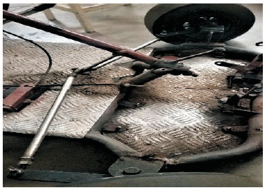
Figure 6. Steering System Side View
Form the steering mechanism, safety and simplicity were the most concerned design requirements. During the designing of steering, the distinct constraints were considered namely center alignment, track width, driver's effort, camber, caster, and the king pin inclination. Due to light in weight, simplicity in design, and low costs, Pivot Pin steering mechanism was chosen. Due to very less number of joints, it allows drivers to take sharp cuts more efficiently. Pitman arm contains set of holes drilled at equal distances by calculations so that tie rods can be adjusted at any time according to the need. This system provides the tendency of varying the sensitivity of steering with use of the multi-hole plate by shifting the ball joints to the next aligned port. This mechanism provides simplicity and directional control for driver over the kart and is shown in Figure 7.
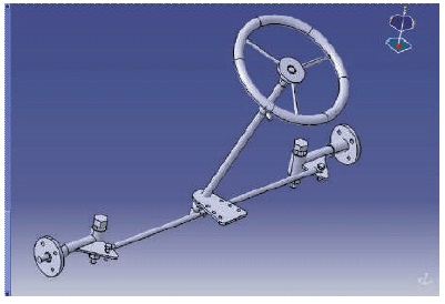
Figure 7. Steering Mechanisms
For the calculations of steering, the following formulae are used.
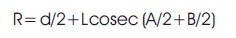
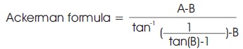
where, R represents turning radius, L represents the length of the car, 'A' is the inside angle of the wheel, 'B' is the outside angle of the wheel, and ‘d’ refers to width of the car. However, equation (2) was used to calculate the Ackerman percentage, A at 30.15° and B at 23°are the best values which can meet desired results and gave radius of turning 1.65 m. When the vehicle is taking a bigger turn, then the geometry will be like Figure 8, where both axel lines intersect with each other making an interaction point and this point is known as an instantaneous center (Figures 8 and 9).
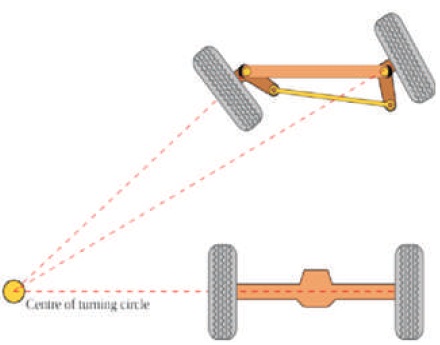
Figure 8. Correct Steering Condition 1
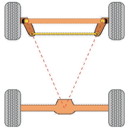
Figure 9. Correct Steering Condition 2
Our tyres exhibit negligible skidding because the inside front wheel carries angle slightly larger than the outside front wheels. Calculations for Inner and outer turning angles are given as follows.
Outer angle: tan A=L(Rd/2),
Inside angle: tan B=L/(R+d/2)
King-pin inclination is induced to make the steering self- returning to some extent or to center itself. If KPI is ~12- 14.2, it imparts self-centering force and takes less effort from the driver to turn hence making it much smooth for turning action. The Go-Kart vehicle steering specifications and Steering design considerations are depicted in Tables 4 and 5, respectively.
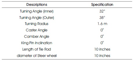
Table 4. Go-Kart Vehicle Steering Specifications
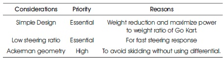
Table 5. Steering Design Considerations
Front axles were also analyzed with the axial load while steering is at work. AISI-4140 material is used for axels. The load on the axle 480 N theoretically calculated were applied in which the induced stress is in the safe range with the F.O.S of 1.85 hence the axle will stay safe considering all data and results during working conditions.
Only one brake disk in the middle of the shaft is used instead of two which results in quick and efficient braking of the vehicle with stability. The different views of brake assembly are shown in Figure 10.
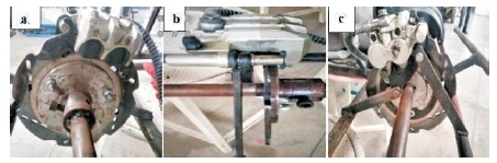
Figure 10 (a). Left Side View (b) Front View ( c) Right Side View of Brake Assembly
To provide more space for driver, master cylinder is mounted at the front section near the brake pedal. Master cylinder bore diameter was determined by doing brake calculations based on the mass, master volume size of cylinder, center of gravity, and other dimensions of the Go- kart.
Calculations: At the time of braking, total kinetic energy of a vehicle is changed into heat because of frictional force between caliper pad and rotor disc during clamping force (Masood, Nihar, Ali, & Sayeed, 2017; Raghunandan, Pandiyan, & Majeed, 2016), Kinetic energy, E= ½ mv2, E=2480 Nm, where, m = mass of kart = 140 kg, v = velocity of the kart = 16.66 m/s. Friction between road and tyres is not exceeding which is about m = 0.60. Hence, the deceleration of the Go-Kart is about 0.60 g or 5.87 m/s2 applying Newton's law of motion formulae. Stopping distance of the vehicle is calculated as v2 = u2+ 2as, where, 'v' represents the final speed of the Go-Kart, 'u' is the initial speed of the kart, and 'S' is distance. When the break is applied, the final speed of Go-Kart becomes zero, while its initial speed is 16.68 m/s. This action decelerates the kart by 0.60 g. Hence, distance of braking, S = 2.51m, time to stop v=u+at. Here, Initial and final velocities are 16.66 and 0 m/s, respectively and distance in which kart stops is 24.62 m. Therefore, t = u/a, t = 2.83 s ,Go-Kart has to be stopped before or on the distance of 2.5 m, therefore.
Braking Force = mx Kinetic Energy/Braking Force
B.F = 634.81 N,
Braking Torque = Braking Force × Effective radius of rotor, B.T. =2200 N.
Driver's force on brake pedal is taken as 102 N (approximately.) and 3:1 is the ratio of pedal. Master cylinder piston area = 1 cm2.
Brake Pressure- B.P = 4 Mpa.
The brake's specifications are shown in Table 6.
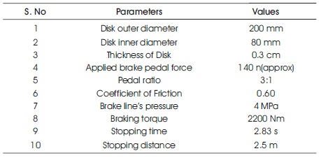
Table 6. Brake's Specifications
Line block diagram of braking system which describes the positions of various components of brake mechanism is represented in Figure 11.
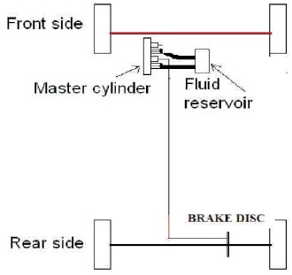
Figure 11. Line Block Diagram of Braking System
The mounting of the brakes was tested with the help of 3D stress analysis. The force of 109 lb was used to drill holes by keeping one side fixed. The resultant is displayed in images below. Deformation of .002 mm (maximum) induced in the analysis was at the topmost point of the mounting. This is almost negligible so it will not cause any effect to the brake mounting design. The master cylinder with mounting, Analysis of master cylinder mounting is depicted in Figure 12 (a) and (b), respectively.
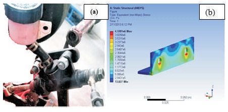
Figure 12 (a) Master Cylinder with Mounting (b) Analysis of Master Cylinder Mounting
The disc brake was also analysed in the thermal module of SolidWorks software. By keeping temperature and convection as the boundary conditions, i.e. (0.8), thermal expansion coefficient, total heat flux as well as heat generation is calculated during the process. The analysis of brake disc is displayed in Figure 13.
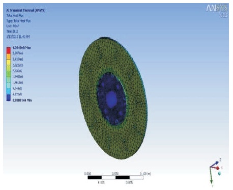
Figure 13. Analysis of Brake Disc
The disc analysis results show the heat flux (4.37×10⁶) W/m2 (maximum), and 200 ºC is temperature of rotating disc at area of contact. It is clear from results that brake disc is under safe zone and will not get deform. From results one can observe that probability of failure of brake due to heat is almost negligible. The Brake design considerations are represented in Table 7.
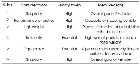
Table 7. Brake Design Considerations
It is a very essential component of the formula vehicles. By considering that all the power output from engine to wheels is transferred through the drivetrain. The main problem that arises here is to extract all the brake horsepower of the engine and equally transmit it to the wheels in the most efficient way. The drivetrain must be able to operate in harsh environmental conditions. The sprocket and chain drive and top view of drivetrain is shown in Figures 14(a) and (b), respectively.
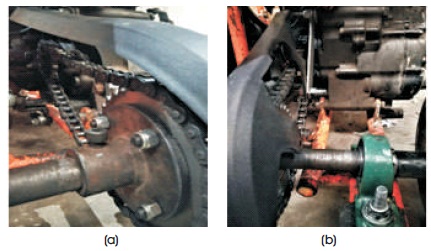
Figure 14. (a) Sprocket and Chain Drive (b) Rear View of Drive Train
Chain drives transfer power from engine to the wheels. The power must be enough to run the vehicle as required. Acceleration which is an essential characteristic also depends on drivetrain. There are many methods to transmit power. This transmission is equipped with sprockets. The rear shaft sprocket is connected via chain to a smaller sprocket in the engine. 26 teeth were taken on sprocket and 13 on engine sprocket to obtain the desired ratio 1:2. This will increase pickup of the Go-Kart. In the engine, sprocket is provided for power output. Finally, chain drive was attached with rear sprocket fixed on the rear axle with engine sprocket. Hence, drive gear ratio came out to be 1:2. This is calculated by - Gear ratio = T1/T2 where, T1 and T2 are the number of teeth on the driver and driven sprockets, respectively. Now Gear ratio=13/26, Gear ratio = 1:2, so the gear ratio of the drive is 1:2, which gives the desired torque for vehicle to come over frictional forces and move.
A four strokes, single cylinder, 11 BHP, and 125 cc aircooled I.C engine has been used for the transmission of power. Go-Kart engine was fixed by the side of the driver's seat on the rigid frame with the anti-vibration mountings. This position of engine reduced wheel base of the kart as it comes next to the driver separated with fire-wall. The final drive is shown in Figure 15.
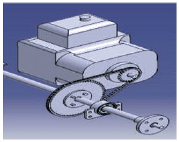
Figure 15. Drive Train Model in Solid Works
After completing full design and analysis, the final design was concluded and then manufactured. The complete 3D views of our Go-kart are shown in Figure 16 and technical specifications of Go-Kart is shown in Table 8.
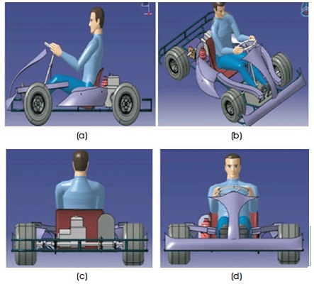
Figure 16. (a) Profile View of Final Design, (b) Side View of Final Design (c) Rear View of Final Design (d) Front View of Final Design
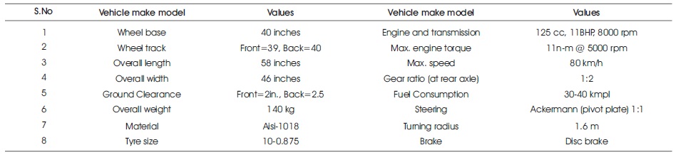
Table 8. Technical Specifications of Go-Kart
Finite Element Analysis (FEA) system was used to create, evaluate, and modify the best vehicle design to achieve its set goals. The main goal was to simplify the overall design to make it more light-weight without sacrificing durability and performance. The result indicate that calculated value of factor of safety (F.O.S) for Go Cart elements is greater than 1. Hence, the design of Go-Cart elements is safe for fabrication using healthy manufacturing practices. In addition, this paper gives an adequate idea about optimum design and analysis of Go-Kart elements.
Go-Karts can be developed by using 4 stroke engine. Bio- Fuels which are of low cost can be utilized in place of diesel/petrol. In addition, non-conventional source (solar energy) can also be utilized by solar panels as they are pollution free with moderate cost. Suspension system can also be added in system to lower vibrations and shocks. Enhancement in the speed of Go-Kart can be done by modifying and providing aero dynamic shape to the Go- Kart body.