(1)

Belt Conveyor system is most preferred and cost efficient bulk material handling system. Rubberized flat belt is the main and the costliest component of belt conveyor system. It greatly affects the overall performance of whole system. For large capacity and long distance conveyor, dynamic characteristics plays vital role. In this paper viscoelastic properties of belts are simplified as a series lump mass and their equation of motion is established by Lagrange approach. Inclined belt conveyor for fully loaded condition is studied as a five degree of freedom problem and its transient performance analyzed by simulating 2nd order differential equations with Simulink. Conveyor displacement, velocity, acceleration and dynamic tension during staring transient process reveals the nonlinear viscoelastic characteristics of conveyor belt. Staring pull is requiring being optimum in view of starting belt stresses and safety of drive motor. Output data helps to improve stability and lower down the factor of safety of belt conveyor system.
Now a days, belt conveyors are used widely as versatile mode for bulk material handling system. It is used in industry fields such as electric power, coal, mines, metallurgy, port, and food supplies etc. Belt conveyor system is capable to handle larger transporting capacity for larger distances and at the lower cost (Woodcock & Mason, 2012). A troughed belt conveyor is an endless, rubberized flat belt running between pulleys at either end and supported by a number of rotating idlers in between. The belt is powered at one of the pulleys (head pulley) and the tension in the belt is maintained by using a gravity take-up unit (Lodewijks, 2002). The material is loaded onto the conveyor at the tail-end and is transported along the carrying-side to the head-end where it discharges. At the loading point impact idlers are located to support the belt where load is dropped down by loading chute. Once the material has been discharged from the carrying belt, the return belt is guided back to the tail pulley on return idlers. The total mass on carrying-side of the belt is greater than the mass to be supported on the return-side thus, to maintain tension in the conveyor belt; idler spacing on both sides is selected accordingly (He, Pang, & Lodewijks, 2016b). Snub pulleys are used to increase the angle of wrap of the belt on the drive pulley, so as to allows more power to be introduced into the belt without slip occurring. Starting of fully loaded belt conveyor is maximum loading condition therefore tractive pull require at drive pulley is decided for this condition (Lodewijks, 2002). This paper studied the transient condition of starting of fully loaded conveyor. Many times belt failure occurs during such condition. Dynamic parameters invariably varies during this period which leads failure of belts. In this paper straight inclined belt conveyor is divided into number of units and it is treated as a continuous lump mass system (Rao, 2007). Equation of motion for each unit is established with help of Lagrange method. Dynamic characteristics observed in the results show prominent variation in the transient period of starting.
Belt conveyor steady state calculation is based on horizontal carrying length. Total mass of the belt conveyer system includes belt mass, bulk material mass, idlers linear inertial mass, snub pulleys mass and drive pulley with drive unit equivalent mass. Idler linear inertial mass is taken as 0.9 of their masses. Snub pulley masses acts 3% to 2% of total mass of system excluding drive unit mass, on carrying and return side of belt respectively. Drive unit including drive pulley adds 7.5% to 17.5% of previously calculated total mass, percentage variation based on the lift of belt conveyor system (Mulani, 2012). Total mass is used for calculation of starting acceleration of the conveyor system to reach desired velocity. Tractive pull as in equation (1) require to start fully loaded belt conveyor system, is to overcome regular resistance offered by inertia of rolling devices, belt over rollers, bulk mass over belt and altitude gradient. The mass quantity is taken for unit length of belt (He, Pang, & Lodewijks, 2016a).
Where,
C = Conveyor length coefficient
f = Conveying friction coefficient
Lh = Belt Horizontal h run distance (m)
mc = Carrying idler rotating mass (kg/m)
mr = Return idler rotating mass (kg/m)
mm = Bulk material mass (kg/m)
mb = Conveyor Belt mass (kg/m)
Hm = Total vertical lift of belt conveyor (m)
Conveyor belt is most important and accounted 30%- 50% of the total conveyor system cost. It is key component of belt conveyor and affects overall performance of the whole system (Conveyor Equipment Manufacturers Association.1997) Traditional calculation of conveyor system uses static method for design with greater factor of safety. However in large capacity and long distance conveyor, dynamic characteristics play vital role and emphasis to study it in accordance. The belt assembly is composed of three elements: top cover, carcase, and bottom cover. Top and bottom cover are of rubber and carcase may be core wire or fabric rope. The belt carcase carries the tension forces necessary in starting and moving the loaded belt and absorbs the impact energy of material loading (Tsalidis & Dentsoras, 1997). During working, rubber and carcase of belt together gives rise to nonlinear characteristic of stress strain, creep and relaxation properties, therefore it has dynamic feature of viscoelastic properties (Lakes & Lakes, 2009; Manjgo, Piric, Vuherer, & Burzic, 2018). Staring of fully loaded belt conveyor is main cause of belt failure. Higher starting pull (1.45 less than 1.7) is considered to start fully loaded belt conveyor to overcome system total inertia (Deutsches Institut für Normun 22101, 2011). High starting pull leads transient condition of the belt at starting phase. During this phase of starting, dynamic responses vary invariably high than the steady state running. These lead to maximum tension at the drive end and maximum stretch in the belt conveyor on carrying side. Staring pull is requiring being optimum in view of generated stresses in belt and safety of drive motor (Bureau of Indian Standards, 2000).
For n degree of freedom system, the equation of motion for a vibrating system is derived by the use of Lagrange's equation. More significantly, the rubber belt exhibits viscoelastic behaviour during operation (Harrison, 1998). Viscoelastic model as shown in Figure 1, formed from a spring and viscous damper in parallel, and it is more close to realistic mechanical properties of the unit.
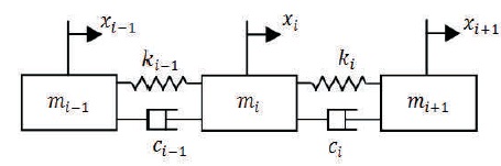
Figure1. Belt i-th Unit Model
The equation of kinetic energy EK potential energy EP and energy dissipation ED of the i-th unit can be written as
Where mi, ki, and ci are mass, stiffness coefficient and damping coefficient of i-th unit. xi represent displacement of i-th unit. Partial derivatives of equation (2) carried out and substituted in the Lagrange equation (3) (Yang, 2014). Thus differential equation of 2nd order obtain, considered as equation of motion for i-th unit (equation 4).
Where wi, the suffered resistance at i-th unit, is considered as non-conservative force and treated additional damping for its unit, varied with velocity of belt. Then rearranging equation (4), the modified equation of motion as (5)
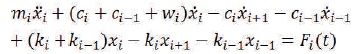
Where mi(t) is external force acting on i-th unit.
Total belt conveyor system is divided in five viscoelastic element, two on carrying side and three on return side of belt system. Take up mass is added equally to its adjacent units. Belt is a viscoelastic material carrying bulk material. In mechanical engineering application belt is modelled as a continuous series of masses with combination of ideal elastic spring and ideal viscous damper connected (Ma, Li, Zhang, & Mao, 2013). The numbering of units is in opposite direction of the motion of the belt as in Figure 2. Each unit was investigated for its equivalent mass, frictional and inertial resistance considering the devices and system part associated with it.
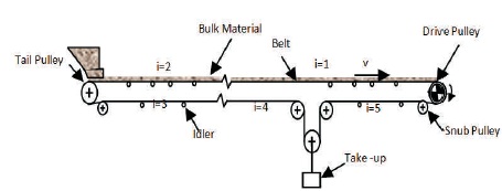
Figure 2. Typical Belt Conveyor System
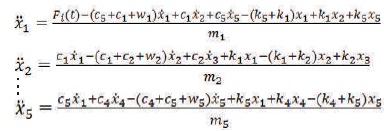
To analyze transient condition of belt conveyor, the belt element lump mass model is built in Simulink. For continuous lump parameter model when i=1, xi-1 = xn and i=n, xi+1 = xi mathematical equation of belt can be expressed as (6)
This paper analyses example of straight inclined conveyor system profile for the bulk lift. Starting dynamics for conveyor belt is simulated for fully loaded condition. Higher staring tractive pull is applied at drive pulley circumference is taken as input to run the simulation.
A ramp function is used between starting pull Ps and steady state pull P, over a time period, till reaching steady state velocity of the whole system. Figure 3 is the representation of 2nd order differential equation with starting pull as input. Stiffness constant ki of each element calculated as a function of Young's modulus of belt and length of unit. Damping constant ci of each element evaluated as dependant value of element mass and stiffness considering critical damping as 0.1. Initial condition at conveyor started as,
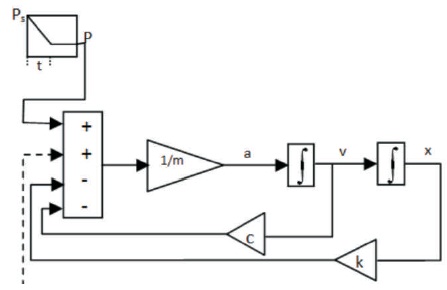
Figure 3. Schematic Equation of Motion
The simulation object is standard CEMA straight inclined single head drive belt conveyer as shown in Figure 4, to transport phosphate rock material. The carrying length of belt conveyor is 304.8 m, the belt speed is 2.54 m/s. Its designed capacity is 1600 tph for lift of 22.86 m. Cross section area of belt is 0.0178 m2 and width of 1.2 m, the belt is tensioned by 2000 kg gravity take-up device

Figure 4. Straight Inclined Belt Conveyor
Belt is driven by lagged and grooved head pulley of diameter 1.07 m with 240o wrap of belt over it. Toughing idlers are Class E6, at 1.07 m spacing and return idlers are rubber disc type, class C6, at 3.05 m spacing.
Observing result of simulation transient condition invariably change during first 20 sec. Transient response obtains indicates that belt conveyer system reaches steady state condition after 50 -70 second of starting. From Figure 5, the tension at drive pulley increases during starting, much higher than the tractive pull applied which is main cause of failure of belt.
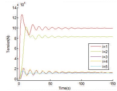
Figure 5. Tension Curves of Conveyor Belt
Greater transient peaks result due to unreasonable start-up mode, shorter start-up time and other factors. Maximum tension in belt is 128 KN near drive pulley unit which stabilizes to 100 KN during steady state running. Smooth acceleration changes can reduce tension peak. Acceleration curves in Figure 6 indicates, within initial 30 sec acceleration changes are more severe. In actual design it is to ensure that acceleration curve peaks should be small to avoid bulk material slippage and excessive wear of belt. Obviously this problem is more prominent near drive end of fully loaded belt.
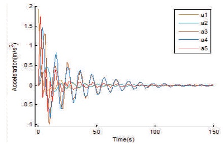
Figure 6. Acceleration Curves of Conveyor Belt
Velocity curves are showing time lags in consecutive units of belt, which shows that the nonlinear stress curve is gradually passed from carrying side to return side. Figure 7 shows speed of conveyor near drive end rise rapidly within 20 s, and reaches to design speed after 70 s.
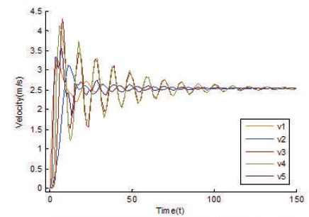
Figure 7. Velocity Curves of Conveyor Belt
The displacement variation of different units with respect to time is shown in Figure 8. Transient variation in displacement between different units causes more stretch in the belt during belt boot up process. This elongation in belt is then converted and adjusted to stroke of the take-up.
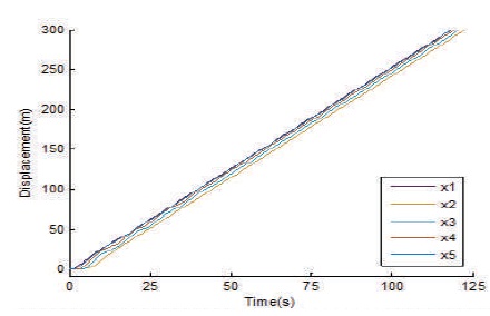
Figure 8. Displacement Curves of Conveyor Belt
Simulation results show that transient condition of belt during starting is prominent at early 30 s. for the case studied the speed of belt rises 70% from its nominal speed. Dynamic tension at drive pulley is maximum and peak up-to 30% of the steady state condition. Designer uses rigid theoretical analysis for large capacity, long distance conveyor design and selection. Simulated result of dynamic system helps to reduce factor of safety used for conveying system. Higher tension at drive pulley unit during starting phase can be lowered down by changing particular angle of wrap and coefficient of friction at drive pulley, which is not covered in this paper. Tractive pull variation is also a function of output torque characteristic of driving motor, which could further give fine dynamic solution.