
Figure 1. Sense - Think - Act Cycle: Functional Decomposition of a Mobile Robot Control System
This paper focuses on exploring and analyzing the process of robot design and hardware implementation of the studies made on the autonomous mobile robot navigation reported in the paper, “Application of Deep Q-Learning for Wheel Mobile Robot Navigation” (Mohanty, Sah, Kumar, & Kundu, 2017). Incorporating autonomous robots into daily life for serving humanity has been a long-term goal for the robotics plethora. An autonomous mobile robot has tremendous application in various environments since they work without human intervention. The robot is defined as a device that is composed of the electronic, electrical, and mechanical systems with a brain imported from computer science. In this paper, a mobile robot is introduced which was fabricated using Raspberry Pi 3 B as a processing chip, range sensors, and camera, which are used for extracting raw sensory data from the environment and feeding it to the robot. The composed mobile robot can be remotely accessed from anywhere around the globe without being in the vicinity of the robot and can be controlled by the means of any gadget, regardless of whether a portable workstation, a versatile, or a tablet, which makes it perfectly suitable for surveillance, exploration, and military applications. For training the robot in the virtual environment, a simulation model was developed in python from scratch. The pre-trained model from the simulation was deployed for further training of the robot in the actual environment. Algorithms like obstacle detection and image recognition were merged together to equip the mobile robot with necessary controls. In the end, the progress of the robot was analyzed in different real environments and the performance accuracy of the obstacle avoidance ability of the mobile robot was calculated based on hit-rate matrices and tabulated.
“A robot is an autonomous system which exists in the physical world, can sense its environment, and can act on it to achieve some goals” (Mataric, 2007). Mobile robots have been getting expanding inquiries about in a colossal scope of uses. In the previous decade, mobile robots have drawn high consideration from both foundation and industry. An autonomous mobile robot is a machine capable of carrying out a complex series of action and locomotion without human intervention. Autonomous mobile robots have potential applications in all kinds of the environment, such as indoor, outdoor, and industrial, underwater exploration, or space exploration. The extensive application of autonomous robots is due to its ability to perform complex tasks without human intervention. While stationary robots can have inflated veracity, mobile robots do not have the potential to accomplish exact scenario due to the coarse limitation of its portable stage. Robots are becoming state of the art due to increment in the computational power, high-quality sensors, a variety of microprocessors and microcontrollers, and a never-ending application in defense. There are numerous microcontrollers in the market comprised of different sorts of ability from essential information yield to top of the line microcontroller. These different sorts of microcontrollers are being developed for the general applications.
The success of autonomous robot involves the integration of knowledge from many disciplines. The fundamental components of robots are (1) perception, (2) localization and mapping, (3) cognition and path planning, and (4) motion control as shown in Figure 1. The successful execution of a task involves synchronization of all its fundamental components (Mac, Copot, Tran, & De Keyser, 2016).
Figure 1. Sense - Think - Act Cycle: Functional Decomposition of a Mobile Robot Control System
Figure 2 exhibits the control architecture of the mobile robot that illustrates the structure and functionality of the mobile robot. The hardware implementation phase is divided into five components. The components are the Raspberry Pi 3, sensors, camera, motor driver controller, and motor in sequential order. Each component has been explained below along with their circuital representation as used in the fabrication of the robot.
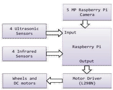
Figure 2. Control Architecture of Mobile Robot
The motivation of this research work was to make an autonomous mobile robot that tries to solve the problem of path planning and navigating using a class of machine learning algorithms known as reinforcement learning (Mohanty et al., 2017). Reinforcement learning algorithms are well suited in the situation where we can model the problem with Markov decision process. Markov decision processes problem are characterized with sets of state S, set of action A, reward R when the states change. Simulation software which was developed by the team during the course of the work was used and then a Raspberry Pi based mobile robot with the obstacle avoidance capabilities was developed for verifying the result.
1.2.1 Hardware Requirements
1.2.1.1 Raspberry Pi 3
The Raspberry Pi as displayed in Figure 3 is a low cost, credit-card sized single board computer system that plugs into a computer monitor or TV, and uses a standard keyboard and mouse. It is a capable little device that enables one to explore computing. It is capable of doing everything one can expect from a desktop computer, from browsing the internet and playing high definition video, to image processing and other high-end computing. Raspberry Pi has the ability to interact with the outside world using its GPIO pins and USB, Ethernet, HDMI, LCD, and camera ports, and has been used in a wide array of digital maker projects, from music machines and parent detectors to weather stations and tweeting birdhouses with infra-red cameras (What is A Raspberry Pi? n.d.; Pajankar & Kakkar, 2016). The specifications of the Raspberry Pi 3 model B which is used in the project is tabulated in Table 1 (Raspberry Pi 3 Model B Brochure, 2016).
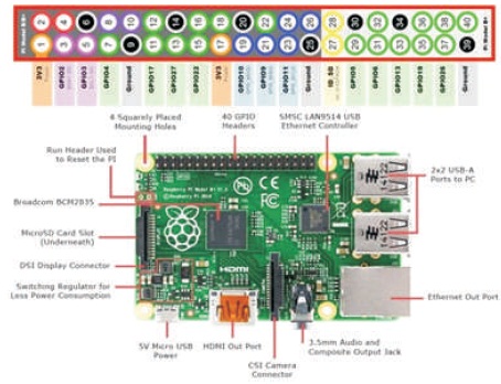
Figure 3. Raspberry Pi 3 Model B (Gonzalez, 2018)

Table 1. Raspberry Pi Features
1.2.1.2 Sensors and Sensor Modules
Collision free navigation is considered to be one of the most prominent aspects in a mobile robot otherwise there will be damage to the robot. The idea of ideal navigation for a mobile robot is planning its course from its current position to the target without colliding with obstacles (Joseph, 2015). The use of sensors fulfills that requirement for a mobile robot. A sensor is a device that detects or measures a physical quantity. Mobile robots engage in significant and purposeful interactions with other establishments like insentient target or obstacles, other robots and human users, etc., through sensing and perception for which it needs a pool of sensors in order to shape it reconcilable for practical situations and applications. Sensing capabilities are firmly associated with the ability to perceive without which the sensor data will only be a heap of meaningless figures (Ge, 2006). Sensors are pivotal for the operation of autonomous mobile robots in unknown and dynamic environments about which there is not much of topological information available. All the sensors used are discussed in the following sub-sections.
(i) Ultrasonic Sensor: Ultrasonic sensor also known as ping sensors have their main application in computing the distance of obstacles from the mobile robot for avoiding obstacles. Ultrasonic ranging module HC-SR04 as shown in Figure 4 has been used with a Raspberry Pi to build an ultrasonic distance meter. The module comprises of an ultrasonic transmitter, receiver, and control circuit whose details have been mentioned in Table 2 (HC- SR04 Ultrasonic Sensor, 2017).
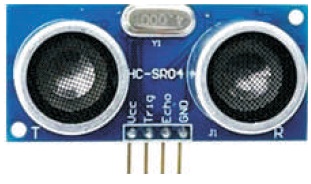
Figure 4. HC-SR04 Ultrasonic Sensor Module (Andrew, 2016)
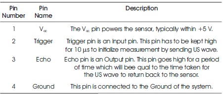
Table 2. Pin Configuration for HC-SR04
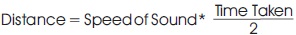
The transmitter of ultrasonic sensor emits a short burst of high frequency sound waves (inaudible to human ears) in a particular direction. The wave bounces off the target and returns to the receiver after a time interval, which can be conveyed from Figures 5 and 6. The time interval is recorded and the distance of the obstacle from the source can be calculated using the following formula:
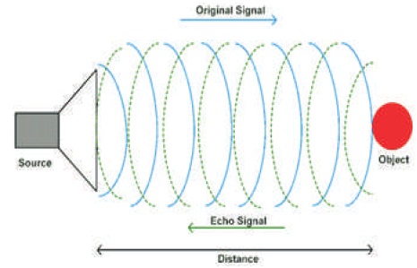
Figure 5. Working Principle of Ultrasonic Sensor (Ultrasonic Module HC-SR04, n.d)
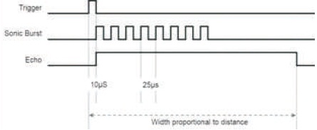
Figure 6. Working of HC-SR04 (Bansal, 2017)
HC-S R04 Sensor Features (Marian, 2013)
Ultrasonic sensors works perfectly until the obstacle is directly in front of the robot. But, if the robot approaches a wall or some other obstacle at an oblique angle, the echo is not received properly leading to miscalculation of obstacle distance. The solution to this is using more than one sensor at different angles allowing them to work together and detecting obstacles that are not in front of the robot (Cicolani, 2018).
(ii) Infrared Sensor: Infrared (IR) sensors are probably the simplest type of non-contact sensors and another method to find obstacles and their distance from the robot and have wide range application in mobile robots for obstacle detection. Sharp GP2D12 infrared sensor as seen in Figure 7 is used in this research work, whose pin configuration has been discussed in Table 3 (GP2D12/GP2D15 Distance Measuring Sensors, n.d).

Figure 7. GP2D12 Infrared Sensor Module (Berl, 2017)
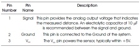
Table 3. Pin Configuration for GP2D12
An infrared sensor consists of two components namely: infrared emitter and receiver. The working principle of IR sensors roots to the infrared light (Wavelength: 700 nm-1 mm, Frequency: 430 THz – 300 GHz), invisible to human eye which is emitted by the infrared emitter which is actually an LED. The infrared receiver accumulates the infrared light that is being reflected from obstacles or target leading to a huge bounce in the intensity of light revealing that there is something in front of the sensor (Joseph, 2015), which is shown in Figure 8.
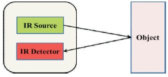
Figure 8. Working Principle of Infrared Sensor
The infrared sensors can be calibrated to measure distance of the obstacles under the presumption that all the objects in the working environment of robot are of uniform color and structure. However, in realistic scenarios the objects have varied colors, shapes, etc., which fluctuates the amount of light being reflected. Due to this, infrared sensors are efficacious only for obstacle detection, but not for range measurement (Nehmzow, 2012).
GP2D12 Sensor Features (GP2D12/GP2D15 Distance Measuring Sensors, n.d)
1.2.1.3 Camera
Camera is considered as a visual sensor since it is used for image acquisition and processing. The Raspberry Pi camera module board allows the use of the Raspberry Pi for real-time video processing purposes. With the module, two new programs were introduced to help the interaction with this new module: raspistill and raspivid. The first one is dedicated to static images, while the second one to record videos. The Raspberry Pi Camera Board features a 5 MP (2592×1944 pixels) Omnivision 5647 sensor in a fixed focus module. The module can be attached to Raspberry Pi by a 15-pin ribbon cable, to the dedicated 15-pin MIPI Camera Serial Interface (CSI), which was designed especially for interfacing the cameras. The still picture resolution is 2592 x 1944 and the video resolutions are 1080p @ 30fps and 720p @ 60fps (Camera Module, n.d).
1.2.1.4 Other Hardware Parts
(i) Motor Driver: A robot's locomotion is based on differential drive system, which involves two wheels and two motors to operate them. Caster wheels are also included to support the main wheels. The robot can be mobilized in any fashion in a 2D plane by varying the velocities and direction of the motor and voltage supplied too. Motors can rotate clockwise or counter clockwise, if we change the polarity of motor terminal. To gain the control of wheel's velocity and direction, the motors should be hinged with a motor controller or driver, which will accomplish these tasks (Joseph, 2015).
L298N motor driver module (Figure 9) is used in the work, which controls a couple of DC motors simultaneously and allows the motors to drive on either direction. The L298N receives signal from the Raspberry Pi and transmits the relative signal to the motors. It has two voltage pins, one of which is used to draw current for the working of the L298N and the other is used to apply voltage to the motors. The L298N switches its output signal according to the input received from the microprocessor (Boxall, 2014). The pin configuration and truth table for L298N motor driver are presented in Tables 4 and 5, respectively (How to use the L298N Dual H-Bridge Motor Driver, 2013).
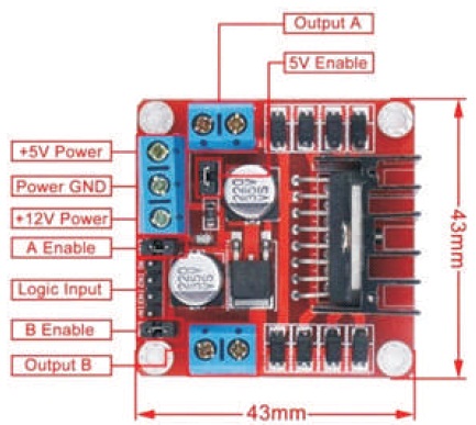
Figure 9. L298N Motor Controller (Muhammad, 2017)
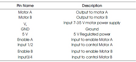
Table 4. Pin Configuration for L298N
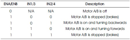
Table 5. L298N Motor Driver Truth Table
L298N Motor Driver Features (Wiring & Driving the L298N H Bridge with 2 to 4 DC Motors, n.d)
1.3.1 Raspbian for Raspberry Pi
Raspbian (Raspbian Documentation, n.d) is a free operating system based on DebianLinux, which has been optimized specially for the Raspberry Pi. It enables one to run a Raspberry Pi like any other Linux computer. Raspbian is highly optimized for the Raspberry Pi line's low-performance ARM CPUs. Also, Raspbian supports meta-OS like Robot Operating System (ROS).
1.3.2 Robot Operating System (ROS)
ROS (Quigley, Gerkey, & William, 2015) is an open source flexible framework for writing robot software. It is a collection of tools, libraries, and conventions that aim to simplify the task of creating complex and robust robot behavior across a wide variety of robotic platforms. From drivers to state-of-the-art algorithms, and with powerful developer tools, ROS has all the required components.
1.3.3 PiCamera Module of Python
PiCamera (PiCamera, n.d; Norbom, 2013) python module is a pure python interface for Raspberry Pi camera supported for python 2.7 or above or python 3.2 (or above). It is used for taking pictures or videos through Raspberry Picamera.
1.3.4 Tensor Flow Module of Python
Tensor Flow (Zaccone, 2016) is a multipurpose open source software library for numerical computation using data flow graphs. It was originally developed by Google Brain Team to conduct machine learning and deep neural networks research. It has been designed with deep learning in mind, but it is applicable to a much wider range of problems. Tensor Flow provides an extensive suite of functions and classes that allow users to build various models from scratch. Tensor Flow provides primitives for defining functions on tensors and automatically computing their derivatives.
1.3.5 PuTTy Program
PuTTY is a versatile terminal program for Windows. It is implemented to control the Raspberry Pi wirelessly.
A simulator named “Green Agent Simulator” as exhibited in Figure 10 was developed from scratch in Python. Name and interpretation of working classes implemented in the “Green Agent Simulator” is presented in Table 6. The step by step detailed procedure for training and testing the “Green Agent Simulator” has been described using the flow chart shown in Figure 11.
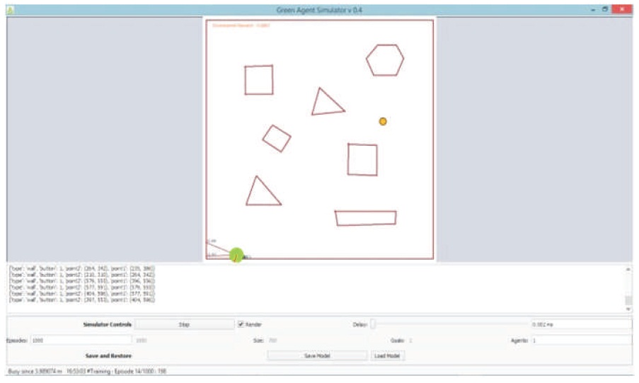
Figure 10. Green Agent Simulator
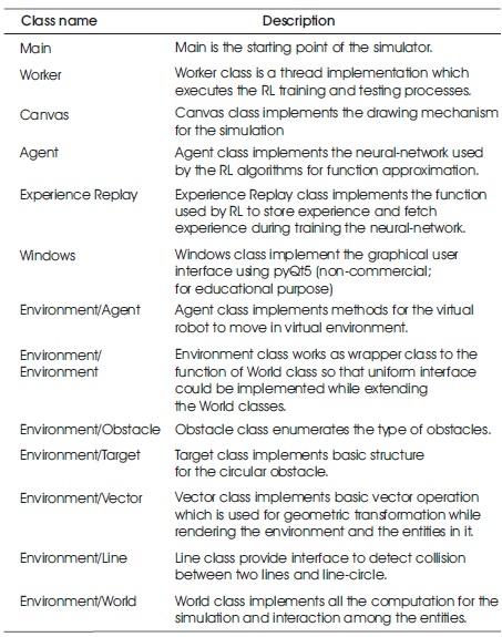
Table 6. Working Classes Implemented in Simulator
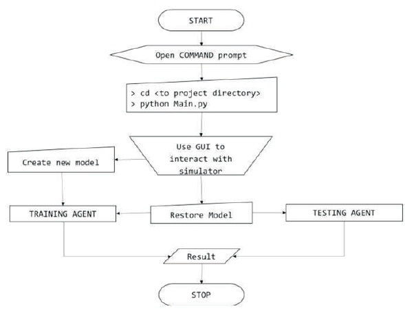
Figure 11. Flow Chart for using Green Agent Simulator
Mobile robot interface is minimal in the form of command prompt application. It uses varieties of worker classes. The main changes comprise of the complete removal of the simulator code as the robot was interacting with the actual world and simulation code was not required anymore. Various sensor controllers were also implemented, such as Motor Controller, IR Controller, US Controller, and Camera Controller. The detailed process of using the mobile robot made by the team as shown in Figure 13 has been explained using a flow chart displayed in Figure 12.
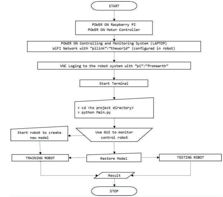
Figure 12. Flow Chart for using Mobile Robot
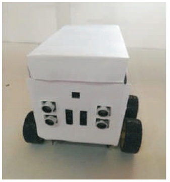
Figure 13. Mobile Robot Developed by the Team
This section provides the circuit diagram of the component connections as done in the robot which is shown in Figure 1A in the Appendix section. In the circuit diagram, solid lines represent live wires (Vcc), dashed lines represent ground, and the dotted lines represent the wires through which information is transferred from Raspberry Pi to the actuators and vice versa.
In the initial training period, since the robot was unknown to the environment, it failed to accumulate high running reward per episode. But as the training proceeds, the agent became better at accumulating rewards as concluded from Figure 14, which signifies the role of deep reinforcement learning.
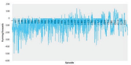
Figure 14. Running Reward per Episode vs. Episode
Multiple experiments were performed on the simulation agent as well as the hardware robot. A few of the simulation results and the corresponding hardware validation result are being presented in Table7.
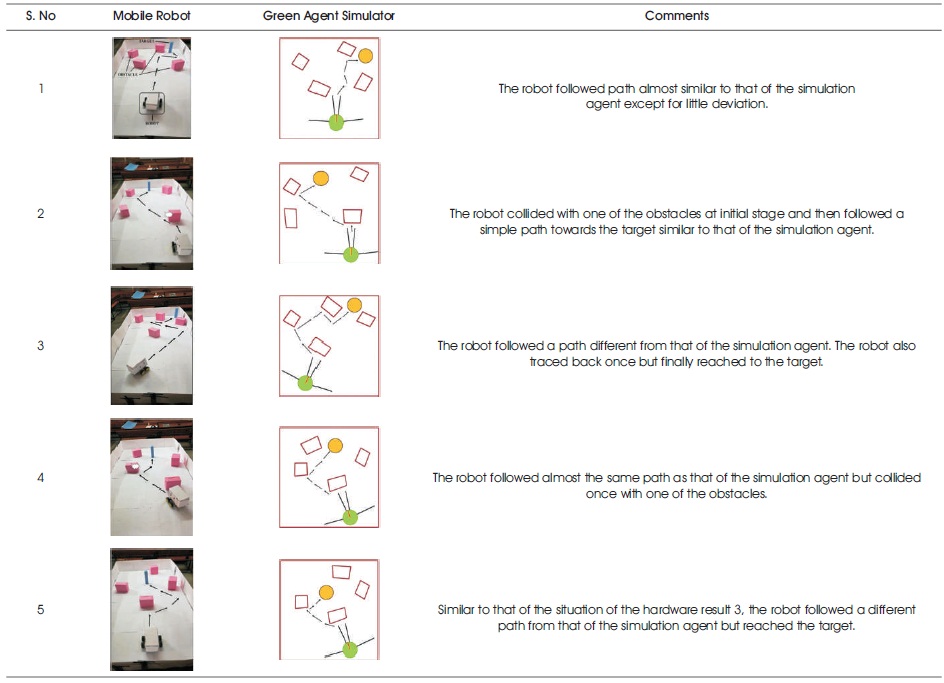
Table 7. Comparison of Experiments on Mobile Robot and Green Agent Simulator
A mobile robot was developed that successfully detects and avoids the obstacles. After the experiments, it was concluded that the robot is able to detect and avoid obstacles with an average accuracy of 90% according to Table 8. The equation of calculating the accuracy is

In the above given formula, the numerator denotes the total number of times the robot was able to avoid the obstacles. The denominator denotes the total number of test cases.
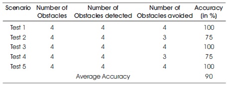
Table 8. Accuracy Measurement of Robot
A mobile robot with obstacle avoidance abilities was fabricated using Raspberry Pi and range sensors, using the algorithms developed for the simulation software. The algorithms were tested in both “Green Agent Simulator” as well as the hardware robot and on analysis exhibited improvement in their performances with the passage of time. It is easy to train the simulator agent, but it gets rigorous and time consuming in the case of hardware robot due to constraints like time, speed, and power henceforth, becoming the major challenges in training the hardware robot. Finally, the simulation results were validated with the experimental results for the motion planning ability of the mobile robot with respect to the time, yielding satisfactory results.
To enhance the work, a few improvements can be incorporated in the robot like IR- sensors with ADC (Analog- Digital) Convertor can be used to have precise obstacle distance measurements. Also, Stereo-vision camera can be used so that the robot will be aware of its environment with precise environment information. The number of IR sensors can also be increased to extract more information about the environment, which could be fed to the system for making decisions. GPS and large IMU sensors can be used along with the 3D sensors so that the robot can perform SLAM (Simultaneous Localization and Mapping). Using solar cell will decrease the redundancy on charging batteries and the robot will be able to charge itself automatically. At present, this work is based on a single agent-system, but can be extended for multiple agent-systems altering few logics.
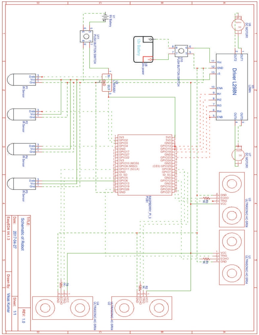
Figure 1A. Circuit Diagram of the Components Connections