(1)
The processes of humidification and dehumidification (HD) are based on the fact that air can be mixed with quantities of vapor. When airflow is in contact with salt water, air extracts a certain quantity of vapor. On the other hand, the distilled water is recovered by maintaining the humid air in contact with cooling surfaces. A wide range of thermal energy including solar, geothermal, exhaust gases, and fossil fuel may be used to operate HD desalination systems. These systems are suitable for arid areas, and when the demand for fresh water is decentralized. In the present work, the influence of the feed salinity and air flow rate on the thermodynamic performance is analyzed. It is found that both the performance ratio and the productivity decreases with the increase in the salinity of the feed water. A parametric study is performed to find the effect of the air flow rate on the productivity and the performance ratio of the system. It is found that both the productivity and the performance ratio decreases with the increase in the air flow rate.
Less than 0.1% of the existing water covering 71% of the earth's surface is reachable potable water. Therefore, improving the effectiveness and efficiency of water desalination technology is considered by many as possibly the main challenge of the 21st century (Sharshir et al., 2016a).
Desalination produces freshwater by taking away dissolved minerals from seawater. Industrially settled conventional desalination processes are extensively used to produce fresh water at industrial-scale include multi-effect distillation, multi-stage flashing, and reverse osmosis.
Humidification-Dehumidification (HD) seawater desalination denotes a reasonably moderate desalination technique established on heat and mass-transfer processes. Ordinary atmospheric air is employed as the medium to convert seawater to fresh water. HD seawater desalination involves two processes. Seawater is first converted to water vapor by evaporation into the dry air in an evaporator (humidification). This water vapor is then condensed out from the air in a condenser to yield freshwater (dehumidification). HD seawater desalination runs under more moderate working temperatures (less than 80 °C) and near-ambient system pressures and needs only reasonable flow pressures.
When conventional desalination systems such as thermal and mechanical systems may not be convenient to install due to their large capacity, cost, and lack of conventional energy sources. Humidification-dehumidification (HD) technology could be adapted to produce fresh water for such cases, due to its relatively low cost, low capacity, and the ability to use renewable energy such as solar energy. HD units may be adapted to produce water in public buildings, such as universities, hospitals, commercial centers, and governmental buildings (Zhang & Cheng, 2009).
The enhancement of the thermodynamic performance of HD systems has been considered by many authors. The state of the art concerning the HD technique was presented in (Bourouni et al., 2001).
A comprehensive technical review of solar desalination with a humidification-dehumidification technique was introduced (Parekh et al., 2004). They concluded that though solar desalination units established on the HD principle are in existence for a while, extra work needs to be done to raise the productivity and decrease the cost of the produced water.
Simulation and energy optimization of desalination using ambient air was studied (Hamad & Abdul-Karim, 2005). The objective was to minimize the solar energy requirements for the system for a fixed water recovery amount. Solar energy was used to further heat the feed saline water to 70 oC to enhance the water recovery. In the study, solar energy was reduced by more than 65% by the proposed energy optimization scenario.
Humidification-dehumidification system in a greenhouse for sustainable crop production was presented (Perret et al., 2005). The use of solar radiation in greenhouses to desalinate saline brackish water was proposed as an alternative to providing fresh water for irrigation at Sultanate of Oman.
A detailed review of water desalination using a humidification-dehumidification technique was introduced (Kabeel et al., 2013). They reported that additional design simulation is essential to entirely comprehend the complicated effects of air and water flow rates, the optimum size of different components or elements of the unit and to create an inclusive model for the system.
A mathematical model was constructed to study the effect of various parameters like the condenser surface area, humidifier area, heating capacity, type of packing material, and flow rate of water on the performance of humidification-dehumidification desalination unit (El- Haroun, 2013). It was found that the productivity of the unit increases with the increase in surface area of heat transfer in humidifier when the other parameters remain constant.
A review of solar-driven desalination system using humidification-dehumidification process was presented (Karhe & Ahmad, 2014). They concluded that the HD process presents a very stimulating answer for small units (hotels, country regions, light industry, etc.), especially when new materials are used.
A humidification-dehumidification (HD) solar desalination unit was designed to provide drinking water for remote arid areas. Solar water and solar air collectors were designed to provide the hot water and air to the desalination chamber (El-Kader et al., 2014). They found that the average accumulative productivity of the system in November, December, and January was in the range of 2 to 3.5 kg/m2 day, while the average summer productivity was found between 6 to 8 kg/m2 day in June, and 7.26 to 11 kg/m2 in July and August.
A theoretical study of a humidification-dehumidification solar desalination unit was carried out to increase understanding the effect of weather conditions on the unit productivity (Elhenawy et al., 2015). A mathematical model was formulated, in which the thermodynamic relations were used to study the flow, heat, and mass transfer inside the humidifier and dehumidifier. The unit productivity was calculated along the working day during the summer and winter sessions and was compared with the available experimental results. The average accumulative productivity of the system during winter was ranging between 2.5 to 4 (kg/m2)/day, while the average summer productivity was found between 8 to 12 (kg/m2)/day.
Yassin and Sawalem investigated the use of solar energy in desalination by humidification and dehumidification process. The obtained results showed a great influence of the input variables on the performance of the unit, which helps in selecting and preliminary design of the desalination unit (Yassin & Sawalem, 2015).
The modeling and experimental investigations of a thermally coupled humidification-dehumidification desalination process using a carbon-filled-polypropylene shell-tube column were presented (Cheng & Shichang, 2007). Performance comparison with the other studies shows that the condensate productivity of this carbon filled- plastic column is not lower than that of the copper column, which demonstrates the practicability and feasibility of applying such a plastic column to the humidification-dehumidification desalination process.
Sharshir and his co-authors have presented a hybrid desalination system using humidification-dehumidification and solar stills integrated with the evacuated solar water heater. The proposed hybrid solar desalination system reuses the drain warm water from the humidificationdehumidification unit to feed solar stills to prevent massive water loss during HD desalination (Sharshir et al., 2016b).
A desalination system emphases on the design and performance advance of a lately established solar humidification-dehumidification (HD) desalination system was studied (Siddiqui et al., 2016). The system contained a centrifugal air blower, humidification chamber furnished with two electric water heaters (500 W each), and a condenser. A solar air heater was used before the humidification chamber to preheat the induced ambient air. Experiment set-I was performed without solar air heater and with two electric water heaters, whereas experiment set-II was performed with solar air heater and one electric water heater.
The results showed that daily productivity and Gained Output Ratio (GOR) were pointedly increased in experimental set-II compared to experimental set-I, whereas the Specific Energy Consumption (SEC) and cost per liter of fresh water produced in experimental set-II were significantly reduced compared to that of experiment set-I for the studied range of induced air flow rates.
An experimental investigation of a humidification- dehumidification (HD) desalination system integrated with a Dual Purpose Solar Collector (DPSC) was reported (Rajaseenivasan & Srithar, 2017). The system ability was investigated by varying the flow rate of air, hot water in the humidifier, and cooling water in a dehumidifier. The system distillation capacity was enhanced with the air and water temperature and flow rate of air, hot water, and cold water.
A new Humidification dehumidification process desalination technology was identified (Ghalavand et al., 2014). The results were compared with two conventional methods. It was found that the Gain Output Ratio (GOR) for the proposed method is higher than conventional methods; also the capital cost per product for the proposed method is lower than two others.
The performance of a desalination unit using humidification-dehumidification technology with new corrugated packing aluminum sheets in the humidifier was experimentally investigated by (Ahmed et al., 2017). The results showed that increasing the temperature of inlet water in the humidifier, the humidifier water flow rate, and the dehumidifier cooling water rate pointedly increases the production of distilled water.
The influence of inlet air flow, humidity, and temperature on the thermal efficiency of an evaporation chamber of a solar desalination plant were studied (Akhatov et al., 2016). Analysis of the achieved results shows that the times of the reaching of an optimal evaporation rate and thermal efficiency values depend on the parameters of the component units of a desalination plant (solar air heater, condenser, heat exchanger, etc.), which should be considered throughout the development of a solar desalination plant.
Design recommendations for humidification- dehumidification solar water desalination systems (HDHSDS) were presented (Shalaby et al., 2017). He reported that the productivity of the humidificationdehumidification solar desalination systems significantly increases when the temperature of the feed water increases, on the other hand, the effect of air temperature on the productivity of the HDHSDS is insignificant.
The performance of humidification-dehumidification desalination, in which dehumidification carried out by compression, was studied experimentally by (Ghalavand et al., 2016). The effects of water-to-air ratio, water and air inlet temperatures, operating pressure, and condenser temperature on desalination performance were examined. It was found that the increase in temperature of the feed water and/or inlet air to the humidifier increases the water production rate and Gain Output Ratio (GOR) of the system. The water-to-air ratio showed an increasing- decreasing trend in relation to the water production rate and the GOR of the system; the best water-to-air ratio was found to be 2.0.
The feasibility of utilizing low-grade heat sources such as solar energy or waste heat from industrial processes for desalination was studied (Gude & Nirmalakhandan, 2008). The results of this feasibility study show that the heat rejected by an absorption refrigeration system of the cooling capacity of 3.25 kW along with an additional energy input of 208 kJ/kg of desalinated water is sufficient to produce desalinated water at an average rate of 4.5 kg/h.
The continuity and energy equations are applied, such that steady-state, steady flow is assumed, with negligible change in kinetic and potential energy.
Mass balance:
 are the summation of the inlet and outlet flow rates, respectively and x is the mass fraction of the water. Also:
Here, y is the mass fraction of the dissolved solids.
Energy balance:
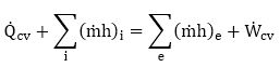
 are the net heat and power flow across the control volume, respectively.
A schematic for the absorber is presented in Figure 1(a). Saline water enters the absorber column from the upper side and air from the lower side. Saturated air leaves the column, emerges into a condenser to condense the distillate water.
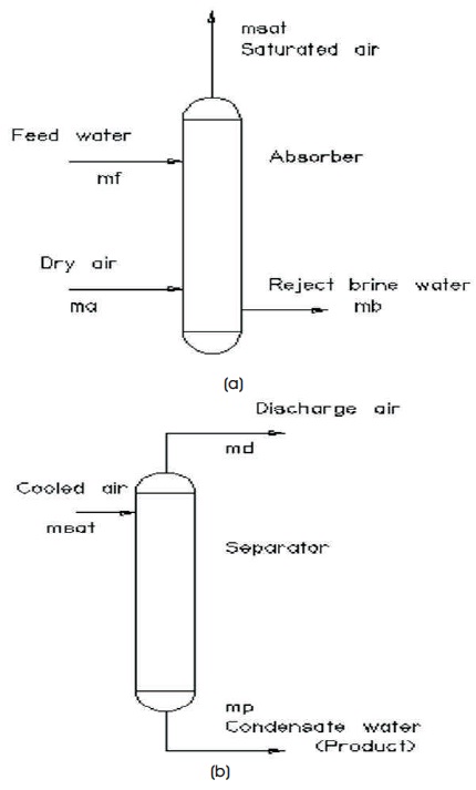
Figure 1. Schematic Diagram for the (a) Absorber, (b) Separator
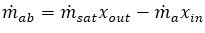
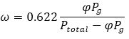
The unit can be planned to restore a definite amount of water. Ambient pressure prevails for the whole process. The amount of water absorbed by air is calculated as (Hamad & Abdul-Karim 2005):
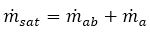
The overall material balance of the absorber is:
From equations (1) and (2), we may have:
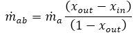
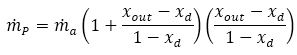
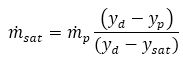
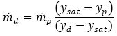
Equation (6) shows that the amount of water absorbed by air is a function of the inlet air flow rate and water mass fraction at the inlet and the outlet of the column. The product water is calculated applying the continuity equation on the separator as follows:
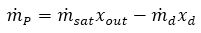
Substitute equation (6) in equation (5) to obtain:
A schematic diagram for the separator is shown in Figure 1 (b). The mass balance reveals that:
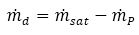
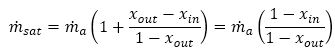
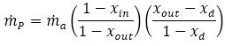
Substituting equations (8) and (9) in equation (7) we will have:
And hence:
Also for the absorber, the mass balance reveals that:
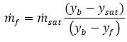
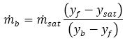
Also for the separator:
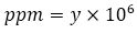
The relationship between the mass fraction of the solids and the ppm is given by:
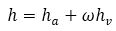
For humid air, the enthalpy is given by:
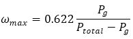
At saturation:
In the proposed system, saline water is heated to increase the water content of the exit stream. Low-grade energy such as solar energy, exhaust gases may be used to heat the saline water. A heat exchanger is also incorporated to heat the saline water by the exit stream, so water is condensed and recovered. The foregoing equation is applied and solved to predict the performance of the proposed system.
The schematic diagram of the proposed system is shown in Figure 2. Saline water (state 1) is mixed with the recycling stream (state 10). The outlet stream (state 2) is heated by using wet air (state 6) coming out of the absorber. Saline water (state 3) is heated by external sources such as solar energy to state (4) before entering the absorber.
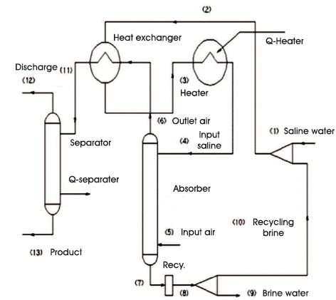
Figure 2. The Proposed Humidification-Dehumidification Desalination Plant
In the absorber, the incoming air, which is introduced at the bottom of the absorber, absorbs the saline water to form wet air (state 6). Part of the brine (state 7) is rejected to the atmosphere (state 9); the rest of the brine (state 10) is mixed with the incoming saline water.
A wet air (state 6) is cooled by the brine water to state (11) before entering the separator, where fresh water (state 13- the product) is separated. Humid air is rejected to the atmosphere at state 12. Mass and energy balance are performed for each component as previously presented.
The input saline water is at 18 oC and 1.0 bar. The ambient dry air enters the absorber at 25 oC and 1.0 bar. The saline water is heated from an external source to 95 oC before entering the absorber. The product water free of solids leaves the separator at 18 oC and 1.0 bar.
To find the effect of the air flow rate into the absorber, the input saline water is kept at 5000 ppm, while air flow rate varies between 0.10 kg/s to 1.0 kg/s.
To find the effect of the input saline water, the air flow rate is kept at 0.50 kg/s, and salinity of the source water varies between 5,000 ppm and 33,000 ppm.
Figure 3 shows the effect of the air flow rate on productivity. As it can be seen, there is a certain point at which the productivity attains its maximum value. In this case, the air flow rate is 0.50 kg/s, beyond which the productivity deteriorates with the increase in the air flow rate.
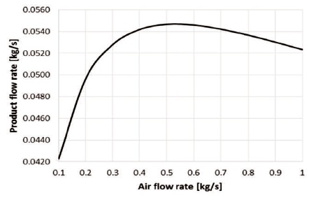
Figure 3. The Effect of Air Flow Rate on Productivity
The main reason for the productivity deterioration is the excessive increase in the amount of water, which is rejected with the discharged air as air reaches the saturation condition in the absorber, this is shown in Figure 4.
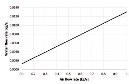
Figure 4. The Effect of the Air Flow Rate on Discharged Water
As it can be seen in Figure 5, more saline water can be fed to the system and as the input air flow rate increases, the relationship between them is not a linear one, and beyond air flow rate of 0.50 kg/s, the feed flow rate of the saline water is almost kept constant at 0.2364 kg/s.
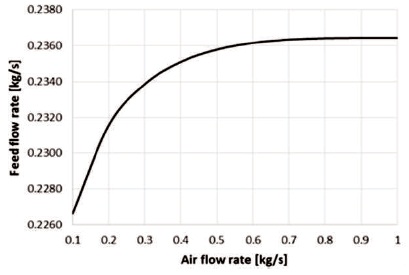
Figure 5. The Effect of the Air Flow Rate on Feed Water
The effect of the air flow rate on the performance ratio is shown in Figure 6. The maximum value of the performance is corresponding to air flow rate of 0.50 kg/s, at which the productivity is a maximum, and the rate of the saline water reaches almost a fixed value of 0.2364 kg/s.
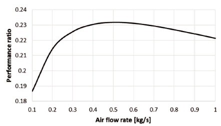
Figure 6. The Effect of the Air Flow Rate on Performance Ratio
Since more saline water can feed to the system with the increase in the air flow rate, the heat supply which is required to raise the saline water temperature to 95 oC, also increases with the increase in the air flow rate, this can be shown in Figure 7.
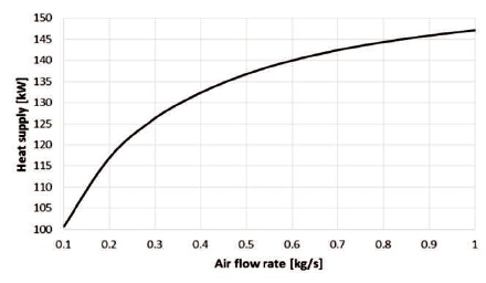
Figure 7. The Effect of the Air Flow Rate on Heat Supply
To keep the product water at 18 oC, heat must be rejected to the atmosphere as shown in Figure 8.
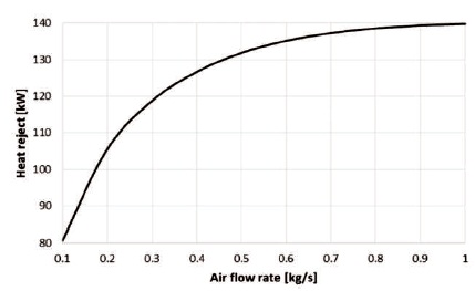
Figure 8. The Effect of the Air Flow Rate on Heat Reject
Figure 9 shows a significant decrease in the disposal of saline water from the absorber up to air flow of 0.50 kg/s, during which both the product and discharged air in the separator increase simultaneously. However, beyond this point, the product water starts to decrease, and hence a gradual decrease in the disposal brine water is noticed.
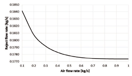
Figure 9. The Effect of the Air Flow Rate on Reject Flow Rate
The salinity of the disposal water is a critical issue from the environmental point of view. As it can be seen in Figure 10, the salinity of the disposal water attains a reasonable value of about 68,600 ppm at an air flow of around 0.50 kg.
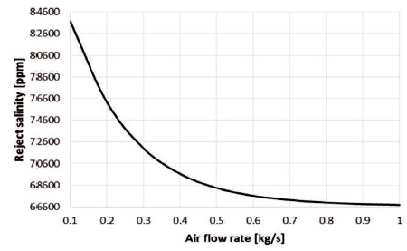
Figure 10. The Effect of the Air Flow Rate on Reject Salinity
As the air flow rate is kept constant at 0.50 kg/s, the product water is almost fixed around 0.05466 kg/s as the salinity of feed water increases from 5000 ppm to 33,000 ppm. However, a significant increase in feed water is occurred, as shown in Figure 11.
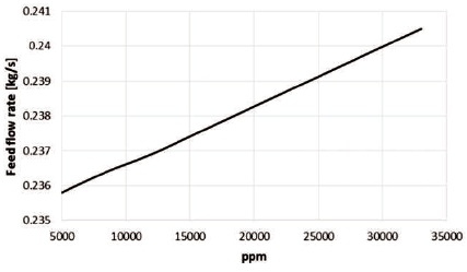
Figure 11. The Effect of the Salinity of the Feed Water on Feed Water Flow Rate
Since the performance ratio is a ratio of the product and feed flow rates, the performance ratio decreases significantly with the increase in the salinity of the feed water and this can be shown in Figure 12.
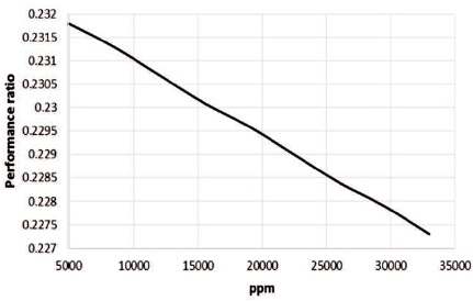
Figure 12. The Effect of the Salinity of the Feed Water on Performance Ratio
It is found that the water content in the discharged air is almost invariant with the feed salinity and attains a value of 0.0065 kg/s. The productivity is also invariant with the feed salinity, and the feed water increases with salinity, then we may conclude the disposal flow rate increases also with salinity as shown in Figure 13.
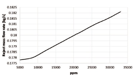
Figure 13. The Effect of the Salinity of the Feed Water on Brine Disposal Flow Rate
As it can be seen in Figure 14, the salinity of the disposal brine water increases significantly with a salinity of the feed water.
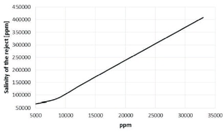
Figure 14. The Effect of the Salinity of the Feed Water on Brine Disposal Salinity
The variation of the feed water salinity does not affect the heat supply and the heat rejection as they attain values of 137 kW and 132 kW, respectively.
A parametric analysis is performed to find the effect of the air flow rate and salinity of the saline feed water on the thermodynamic per formance of a proposed humidification-dehumidification desalination unit. The following points may be highlighted:
For a given salinity of the feed water:
When air flow rate is kept constant at the best performance:
h enthalpy [kJ/kg]
 mass flow rate [kg/s]
P pressure [kPa]
ppm parts per million
 heat transfer [kW] .
 power [kW]
x mass fraction of water
y mass fraction of solids
φ relative humidity
ω humidity ratio
a air
ab absorber
b brine
cv control volume
d discharge
e exit
f feed
g gas (vapor)
I inlet
in at absorber inlet
out at absorber outlet
p product
sat saturation
v vapor