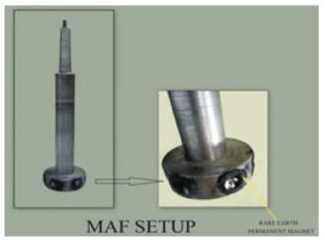
Figure 1. MAF Setup
A magnetic abrasive finishing process is a method of non-traditional precision machining in which the finishing process is completed using magnetic force and magnetic abrasives. In this research, SUS 304 thick cylindrical tube was finished using a magnetic abrasive finishing process with the objective of development of new MAF setup for finishing of Thick Tubes, to study finishing performance of developed MAF setup for internal finishing of stainless steel tubes (SUS 304) using diamond based sintered magnetic abrasives. This paper describes the development of the high-speed multiple pole finishing equipment and the effects of tube rotational speed on abrasive motion during the finishing experiments.
Recent rise in numerous technological fields calls for the change and use of exceptional engineering materials like different types of steels, nonferrous metals, and ceramics. It is hard to finish advanced engineering materials by finishing techniques like lapping, honing, and super finishing economically. Also, processes ought to meet the wants of high surface quality, precision, and least possible surface deficiencies. This has necessitated the event of alternate finishing technologies, namely, Magnetic Abrasive Finishing (MAF) (Shinmura et al., 1990; Lambropoulos et al., 2010; Fox et al., 1994). MAF is a nonconventional method during which workpiece surface is smoothed by removing the material in the type of microchips by abrasive particles surrounded by the presence of magnetic flux within the finishing area (Singh et al., 2003; Saraeian et al., 2016; Lee et al., 2013; Givi et al., 2012 Jain, 2009). The operating gap between workpiece and rare earth magnet is full of a mix of ferromagnetic and abrasive particles (Yamaguchi et al., 2005; Wang and Hu, 2005; Wang et al., 2004). In some attempts bonded ferromagnetic and abrasive particles also are used (Chang et al., 2002; Yamaguchi et al., 2007). These MAPs form a useful Flexible Magnetic Abrasive Brush (FMAB) within the presence of magnetic flux and do not need dressing or sharpening (Sran et al., 2012) . In this research, a SUS 304 thick cylindrical tube was finished using a magnetic abrasive finishing process with the objective of development of new MAF setup for finishing of Thick Tubes. The other objective was to study finishing performance of developed MAF setup for internal finishing of stainless steel tubes (SUS 304) using diamond based sintered magnetic abrasives and to investigate effect of input process parameters (circumferential speed of magnets, mesh number, quantity of abrasives, finishing time) on the performance characteristics like Percentage Improvement in Surface Finish (PISF) using Response Surface Methodology (RSM) and to develop empirical relationship between process input parameters and the process output characteristics by developing regression model and to investigate the interactions between the various input process and their effect on the process output characteristic like PISF. It has been found that mesh number and quantity of abrasives have significant effect on PISF. Results show that interaction of speed and finishing time also has significant effect on PISF. The maximum percentage improvement in surface finish was found to be 94.32% at 310 rpm of speed of permanent magnet, 20 gm of quantity of abrasives, 44 mesh number and 20 minutes of finishing time. In addition, the Scanning Electron Microscope (SEM) photographs shows that the surface generated by boring on lathe consists of deep scratches. The peaks have been sheared off too much smaller height by MAF resulting in improved surface finish, but fine scratching marks produced by MAF appear on the surface.
An experimental setup is attached on radial drilling machine of variable rate, consisting of six permanent magnets (Figure 1) and the workpiece is clamped on the vice of operating table of x-y stage. The permanent magnets fastened within the spindle will rotate at high speed as that of the rate (varying) of rotating spindle of radial drill machine, whereas the workpiece fastened on the operating table is fixed on the machine vice. The diamond magnetic abrasives introduced into the operating gap between the magnetic pole and also the workpiece, are magnetically attracted by the magnetic pole and therefore revolve following the magnetic pole. The magnetic force required to form the FMAB in MAF process is due to the magnetic field produced by a permanent magnet ( Yamaguchi and Shinmura 2000; Jain et al., 2001;; Mori et al., 2003; Yin and Shinmura 2004). The rotor and rotor shaft are machined on lathe. The material used for the rotor and rotor shaft is mild steel. The diameter of the rotor is kept 66 mm, thickness is kept 20 mm, stroke length is kept equal to 70 mm. Six rare earth permanent magnets are fixed inside the rotor circumferentially and the angle between each of the permanent magnet is kept at 60º. These magnets are fixed with the help of epoxy resin in drilled holes made in the rotor circumference. The spindle of mild steel is turned to size 19 mm which is attached to the socket of radial drill machine.
Figure 1. MAF Setup
Before beginning experiments, the workpiece surface finish after boring operation done on lathe machine is measured by Talysurf surface roughness tester at four different places inside the bore of the workpiece. The workpiece is mounted between the jaws of bench vice of radial drill machine. The operating gap is kept constant throughout experiment work. The magnetic abrasive powder that is ready before every run is fed by simply adding the lubricant into the finishing area.
The movement motion to the permanent magnetic setup is given through spindle of the radial drill machine. The finishing operation is sustained for various levels of finishing time and it is monitored with a timer (0.01s accuracy) to exchange an area of the used magnetic abrasive powder within the finishing area by the homogeneously sintered remaining (unused) powder. The workpiece is taken out from its holder once the finishing process is over. After cleaning the workpiece, its surface finish is measured. Surface finish is measured employing a digital surface roughness Talysurf tester having a least count of 0.01 μm. To grip together the mixture of magnetic and abrasive particles for a longer time period, lubricating oil (5% by wt.) is added to the mixture of ferromagnetic and abrasive particles forming a conglomerate. Fresh sintered abrasive is constantly added to maintain its finishing efficiency. The sintered diamond magnetic abrasive separates as it is attracted to the ends of the six magnetic sections. For the experiments, 4 levels in gm of sintered magnetic abrasive (85 wt% iron particles and 15 wt% magnetic abrasive) was introduced. The magnet rotational speeds were varied between 310, 485, 695, and 960 /min.
Finishing experimental conditions are explained in Table 1.

Table 1. Experimental Conditions
Response Surface Methodology (RSM) is used in the present experiment. Four independent parameters, each has four different levels (Yamaguchi et al., 2007) were selected which are: (A) Circumferential Speed (rpm), (B) Mesh No., (C) Quantity of Abrasives (grams), and (D) Finishing Time (Min.) (Table 2). The magnetic abrasive powder used is formed from 85% Fe and 15% Diamond the output data measured is the change in surface roughness (ΔRa) between the arithmetic mean surface roughness (Ra) of the workpiece before and after MAF experiments. Surface roughness tester is used to measure the values of Ra at four different places at same line in the workpiece after MAF taking the average value and then subtract from the average value of Ra before MAF which is obtained from 64 readings of Ra at different places of the workpiece.
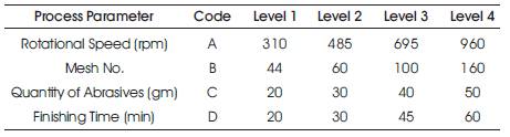
Table 2. Level of Independent Variables
The output response like percentage improvement in surface finish is tabulated and analyzed. Percentage improvement in surface finish is used as a measure of performance of MAF. The results of different experimental investigation carried out under present study are in the form of table, graph, and response analysis. The scanning electron microscope images of the magnetic abrasive finished workpieces were taken to provide in depth comparison of the surface generated before and after MAF. The average values of the response characteristics were calculated from experimental data and the response curves were plotted to show variation of process output characteristics. Analysis of variance (ANOVA) on the data was performed to identify the significant parameters and to quantify their effect on the response characteristics. The effect of the individual MAF process parameters on the above mentioned response characteristic is also presented.
Second-order response surface models using the process parameter were developed as:
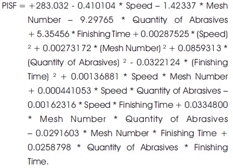
The coefficients of the independent parameters show the extent of influence of the parameter. Higher the numerical value of a coefficient, greater would be the influence of the parameter. If a coefficient is positive, then with an increase in the value of the parameter, the optimization parameter grows and vice versa.
Total 16 experiments were performed to study the effects of various independent variables on percentage surface improvement. The independent variables of the process are Circumferential Speed in RPM (A), Mesh Number (B), Quantity of Abrasives in Grams (C), and Finishing Time in Minutes (D). The different tests were applied to select the adequate model that fits the output characteristic namely PISF. The “Sequential Model Sum of Squares” test shows how the degrees of polynomial that may be selected for the model contribute to the complexity of the model. The effects of interactions of different process parameters, such as circumferential speed of the magnet, Mesh Number, Quantity of abrasives, and Finishing Time on Percent Improvement in Surface Finish (PISF) were analysed using Response Sur face Methodology (RSM). The process yielded best results at Speed (A) - 310 rpm, Mesh Number (B) - 44 Mesh, Quantity of Abrasives (C) - 20 grams, Finishing Time (D) - 20 minutes. The 3D graphs show the effect of simultaneous variation of two factors on PISF.
Figure 2 shows the relationship between the Quantity (C) and Finishing Time (D), keeping the value of Speed (A) and Mesh Number (B) to a constant level. As the Finishing time increases at higher level of quantity of abrasives, the surface finish improves, but decreases at lower levels of quantity between 25 gm and 30 gm. The surface finish is better at higher values of quantity, and as the finishing time increases the surface finish increases. Figure 3 shows the relationship between the Mesh Number (B) and Finishing Time (D), keeping the value of Speed (A) and Quantity of Abrasive (C) to a constant level. As the Finishing time and Mesh Number increases, the surface finish improves, but start decreasing at higher levels of Mesh Number and finishing Time. With increasing the value of Mesh Number and Finishing Time, the value of PISF goes on increasing at different rates, reaches maximum value before it starts decreasing. Figure 4 shows the relationship between the Mesh Number (B) and Quantity of Abrasive (C), keeping the value of Speed (A) and Finishing Time (D) to a constant level. As the Quantity of abrasives increases, the surface finish improves, but start decreasing at higher Mesh Number.
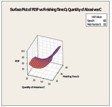
Figure 2. Surface Plot of Percentage Improvement in Surface Finish vs. Finishing Time and Quantity of Abrasives
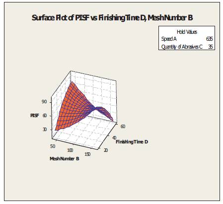
Figure 3. Surface Plot of Percentage Improvement in Surface Finish vs. Finishing Time and Mesh Number
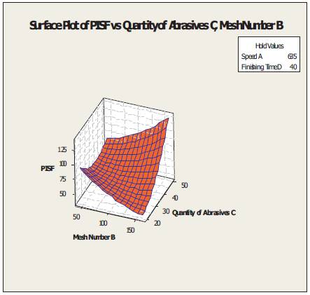
Figure 4. Surface Plot of Percentage Improvement in Surface Finish vs. Mesh Number and Quantity of Abrasives
Figure 5 shows the relationship between the Rotating Speed (A) and Finishing Time (D), keeping the value of Quantity of Abrasives (C) and Mesh Number (B) to a constant level. As the finishing time and circumferential speed increases, the surface finish improves, but start decreasing between speed level 500 rpm – 600 rpm of circumferential speed. With the increasing value of circumferential speed and finishing time, the value of PISF goes on increasing at different rates and reaches maximum value. Figure 6 shows the relationship between the Rotating Speed (A) and Mesh Number (B), keeping the value of Quantity of Abrasives (C), and Finishing time (D) to a constant level. As the mesh number and circumferential speed increases, the surface finish improves but start decreasing between speed level 600 rpm to 800 rpm of circumferential speed. With the increasing value of circumferential speed above 800 rpm and mesh number, the value of PISF goes on increasing at different rates and reaches maximum value.
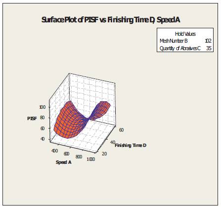
Figure 5. Surface Plot of Percentage Improvement in Surface Finish vs. Finishing Time and Speed
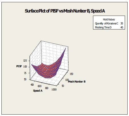
Figure 6. Surface Plot of Improvement in Surface Finish vs. Mesh Number and Speed Percentage
Figure 7 shows the relationship between the Rotating Speed (A) and Quantity of Abrasives (C), keeping the value of Mesh Number (B) and Finishing time (D) to a constant level. As the mesh number and circumferential speed increases, the surface finish improves remarkably and the value of PISF goes on increasing at different rates and reaches maximum value.
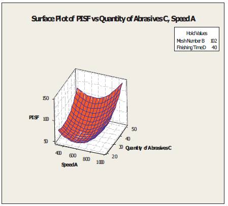
Figure 7. Surface Plot of Improvement in Surface Finish vs. Quantity of Abrasives and Speed Percentage
The surface structure was analyzed by SEM before and after finishing SUS 304 Steel tube. The characteristic SEM micrographs of as received after boring the workpiece and magnetic abrasive finished surfaces are shown in the figures. The primary surface profile has periodic crests and troughs produced by boring. The observational SEM photographs communicate that finishing of workpiece surface in the procedure is done by scratching or microcutting. It is quite clear from Figure 9 that the deep cutting marks left by the boring operation have been removed and replaced by the new texture generated during the MAF process as shown in Figures 8 and 9, but fine scratching marks produced by MAF appear on the surface. Most of the crests have been sheared off to much smaller height by MAF leading to improved surface finish. Moreover, the micrograph reveals clearly the presence of unfinished surface with non-uniformity over the outer layer of the workpiece (Figure 8). Some deep scratches appear when finishing operation was performed at higher rotational speed. Also, some scratches can be seen when finishing was performed using greater finishing time.
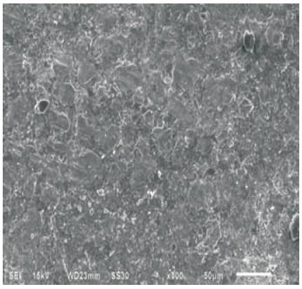
Figure 8. SEM Microphotograph of Surface Finished by Boring (Avg. Ra = 4.58 μm)
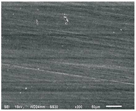
Figure 9. SEM Microphotograph of Surface Finished by MAF at Speed 310 rpm, 44 Mesh, 20 gm of Abrasive Quantity, 20 min. Finishing Time (Avg. Ra =0.26 μm)
The following conclusions are drawn from the present study on 'Development and performance evaluation of magnetic finishing setup for thick cylinders'. Rotational speed (A), Mesh Number (B), Quantity of Abrasives (C), and Finishing Time (D) is effecting the Percentage Improvement in Surface Finish (PISF). The parameters Quantity of Abrasives (C), Finishing Time (D), and Mesh No. (B) significantly affect the percentage improvement in surface finish (PISF). There is a significant effect of interaction of Circumferential Speed (A), Mesh No. (B), Quantity of Abrasives (C) on percentage improvement in surface Finish. The process yielded best results at speed (A)- 310 rpm, Mesh Number (B)- 44 Mesh, Quantity of Abrasives (C) -20 grams, Finishing Time (D) -20 minutes. The SEM examination demonstrates that the completed surfaces have fine scratches and micro scale cuts that are more remote, far off separated instigating smoothed surface.
The authors gratefully acknowledge the technical support provided by IKG Punjab Technical University, Kapurthala, India for carrying out this work.