Figure 1. Simulation Model of SPWM Inverter Fed Squirrel Cage Induction Motor i-
In the present time, many Pulse Width Modulation (PWM) techniques are being used with induction motors to achieve variable speed for more efficient performance of the motor. The main task of the PWM technique is to achieve variable voltage and frequency supply from a three-phase voltage source inverter. The drives based on sinusoidal pulse width modulation control technique have been accepted widely in industry with reduced harmonics in the inverter voltage. Yet due to developments in power electronics and semiconductor technology it provides the authors with significant scope for further improvements in inverter voltage for better controlling performance of the induction motor. Through further reduction of harmonics, the inverter voltage is achieved in this paper by a new space vector pulse width modulation technique efficient with many advantages. In this paper, the Sinusoidal PWM and Space vector PWM inverter fed induction motor drives models have been proposed and simulation is done in the latest MATLAB simulation environment. It is observed that the Space vector PWM inverter gives encouraging results as compared to Sinusoidal PWM Inverter. In the future, the Space vector PWM control technique might be used in industry in place of Sinusoidal PWM control technique with efficient performance.
Inverters convert DC power into AC power at desired frequency and output voltage. Though the voltage is highly dependent on the switching states of the power semiconductor devices based switches used in the inverter (Siddiqui et al., 2014; Krause and Thomas, 1965; Bose, 1986; Holtz, 1992; Zhou and Wang, 2002 ; Wang, 2002; Kumar et al., 2010). Nevertheless, the main drawback of an inverter is that it introduces harmonics into the voltage, current, and developed electromagnetic torque of an induction motor (Siddiqui et al., 2015; Hassankhan and Khaburi, 2008; Hartani and Miloud,2010). For inverter fed induction motor drives, it is extremely important to choose suitable PWM control techniques with minimum harmonics for proper operation of the induction motor.
Generally, the SPWM inverter technique has been used with an induction motor in many applications and this technique is popularly used in industry. Yet, the SPWM control technique produces large harmonics in the inverter output voltage. And in the inverter fed induction motor drives, the large variation in the motor speed is not possible by SPWM control technique (Siddiqui et al., 2015; Hartani and Miloud, 2010; Howard and Murphy, 1992). To this end, this paper is an attempt to solve the above problem by SVPWM control technique.
At the present time, Digital Signal Processing (DSP) techniques are used with an induction motor for better accuracy and performance. The DSP techniques are also used in the fault diagnosis of an induction motor. The implementation in the digital circuitry of the SPWM control technique is not easy because it produces large harmonics in the inverter voltage, consequently a fundamental component of the voltage is decreased (Siddiqui et al., 2015; Hassankhan and Khaburi, 2008; Hartani and Miloud, 2010; Howard and Murphy, 1992). This problem will also be solved in this research paper by introducing SVPWM inverter fed induction motor drive simulation model. The same rating induction motor will be used with SPWM and SVPWM control techniques for a more efficient or higher performance comparison.
The SVPWM control technique is used to compute duty cycle of power electronics switches consequently, the digital implementation of PWM modulators is done. The SVPWM technique enables easy digital implementation and with wide linear modulation range for output line-toline voltages (Wang, 2002; Siddiqui et al., 2015;Hassankhan and Khaburi, 2008).
The squirrel cage induction motor is always a better choice in industry for a large number of applications. The basic advantages of squirrel cage induction motor is its simple construction, high reliability, and the availability of power converters based on efficient control strategies (Siddiqui et al., 2014; Krause and Thomas, 1965; Bose 1986). In this paper, the performance analysis of the squirrel cage induction motor was achieved through different PWM control techniques.
The mathematical analysis of SVPWM control technique has been discussed by Siddiqui et al. (2015). The open and closed loop SVPWM inverter fed induction motor models have also been discussed. The mathematical modeling of squirrel cage induction motor was analyzed in Siddiqui et al., (2014).
The main aim of this research paper is the simulation and performance comparison of SPWM and SVPWM control techniques fed with squirrel cage induction motor in the transient condition. The harmonic analysis has also been done for both simulation models.
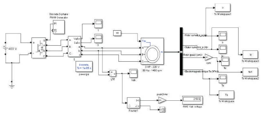
The transient dynamic SPWM inverter fed squirrel cage induction motor simulation model is shown in Figure 1. This simulation model is used for analysis purpose with SPWM control.
Figure 1. Simulation Model of SPWM Inverter Fed Squirrel Cage Induction Motor i-
The specifications of the used induction motor are as follows:
The parameters of the inverter are as follows:
In the simulation model, for simulating the effect of smoothing reactor, the leakage inductance of the stator is set two times to its original value and motor's inertia prevents the noise introduced by pulse width modulated inverter.
The stationar y reference frame is used in the transformation from abc to dq or vice versa. All dq variables, simulation speed, and also accuracy of results will be affected by this reference frame. Therefore, one needs to choose correct reference frame as per necessity of the application.
The line to line nominal Root Mean Square (RMS) voltage of the squirrel cage induction motor is obtained 220 V by the given equation:
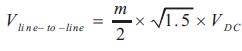
The simulation results in balanced supply or symmetrical (or called healthy mode) motor condition of the induction motor are as shown in Figure 2. Four squirrel cage induction motor signals are used for analysis purpose; those are stator current, rotor current, rotor speed, and electromagnetic torque. In the balanced state of the induction motor, the slip is set at 1(s=1) and mechanical torque is 15 N-m. From obtained simulation results, it has been observed that all four motor signals are reached in the steady state condition after 0.4 seconds. The motor's speed is reached (i.e. 1430 rpm) in the steady state after 0.4 s as shown in Figure 2(c).
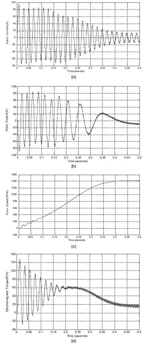
Figure 2. Balanced Condition of the Induction Motor, (a) Stator Current, (b) Rotor Current, (c) Rotor Speed, (d) Developed Electromagnetic Torque
It was observed in the starting procedure of the motor, the first peak of the stator current and electromagnetic torque waveforms had the highest amplitude until it decreased and reached its stable condition. The model was simulated for 0.5 s to produce a clear visualization of its transient characteristics. And then the transient characteristics of the motor could be clearly observed and analysed.
The motor starts and reaches its steady state speed 1430 rpm after 0.4 s. At start up, the magnitude of the 50 Hz current reaches 96 A peak (68 A RMS) whereas its steady state value is 12.25 A (8.66 A RMS). Therefore, the magnitude of the 50 Hz voltage contained and in the chopped wave stays at 220 = 311 V.
The developed electromagnetic torque of the induction motor is as shown in Figure 2(d). The developed electromagnetic torque is reached in the stable state after 0.4 s. At the start-up of the motor, strong oscillations are observed in the developed electromagnetic torque. If the authors zoom in on the torque in steady state, the authors will observe a noisy signal with a mean value 15 N.m, corresponding to the load torque at nominal speed.
The motor currents shown in Figure 2(a) observes that all the harmonics (multiple of the 1650 Hz switching frequency) are filtered by the stator inductance; hence, it can be stated the 50 Hz component is dominant. The rotor current signal at standstill is as shown in Figure 2(b). Also this signal reaches the steady state after 0.4 s.
The harmonic analysis of SPWM inverter fed induction motor has been done for two signals; first is inverter voltage and second is stator current. The inverter voltage signal along with Total Harmonic Distortion (THD) is shown in Figure 3(a). The magnitude of the fundamental of the inverter voltage (311 V) is compared well with the theoretical value (311 V for m=0.9) as shown in Figure 3(a).
Figure 3. (a) THD in Inverter Voltage, (b) THD in Stator Current
Harmonics are displayed in percent of the fundamental component. As expected, harmonics occur around multiples of carrier frequency (n×33 ± k). Highest harmonics (30%) appear at 31th harmonic and 35th harmonic (33+2). It can be clearly seen in Figure 3(a). Note that, the THD value for voltage (80.25 %) has been computed for maximum frequency 2500 Hz.
The harmonic analysis of stator current of the motor has also been done and shown in Figure 3(b). The THD in current has been observed 18.35% along with fundamental component 80.6 A.
In the next section, the same induction motor will be used for an analysis purpose along with SVPWM control technique for further improvement.
In this section, the squirrel cage induction motor fed into SVPWM inverter control has been used for analysis purpose as shown in Figure 4(a). The SVPWM 'modulator block' is used to generate firing pulses. The chopping frequency is computed to 1650 Hz and the 'magnitudeangle' is input reference vector. The constant V/f block has been used in controlling the speed of the induction motor as shown in Figure 4 (b). All parameters and specifications of the motor and inverter are same as the authors used in the previous section.
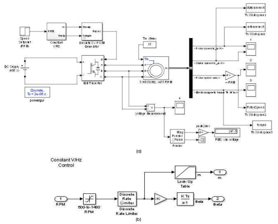
Figure 4. (a) SVPWM Inverter fed Squirrel Cage Induction Motor Model, (b) Constant V/f Control Sub-Model
The simulation results in balanced supply or symmetrical (or called healthy mode) motor condition of the squirrel cage induction motor are as shown in Figure 5. Four squirrel cage induction motor signals are used for analysis purpose; those are stator current, rotor current, rotor speed, and electromagnetic torque. In the balanced state of the induction motor, the slip is set at 1(s=1) and mechanical torque is 15 N-m. From obtained simulation results, it has been observed that all four motor signals reach the steady state condition after 0.25 s. The motor's speed is reach (i.e. 1455 rpm) the steady state after 0.25 s as shown in Figure 5(c).
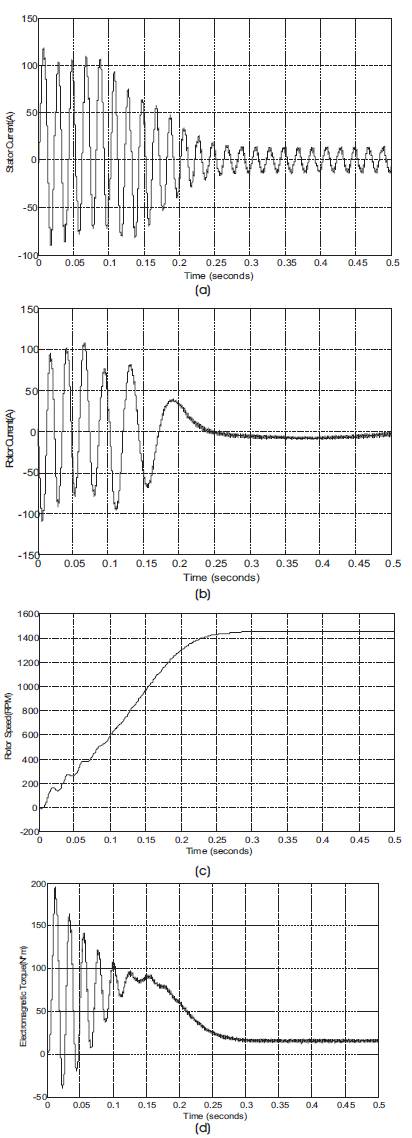
Figure 5. Balanced Condition of the Induction Motor, (a) Stator Current, (b) Rotor Current, (c) Rotor Speed, (d) Developed Electromagnetic Torque
It has been observed that in the starting of the motor, the first peak of the stator current and electromagnetic torque waveforms as shown in Figures 5(a and d) have highest amplitude after which they decrease and reach the stable condition. The rotor current at stand still is as shown in Figure 5(b). The rotor current is reached in the stable state after 0.25 s.
The model is simulated for 0.5 s for clear visualization of t ransient characteristics.Therefore, transient characteristics of the motor may be clearly observed and analysed.
The harmonic analysis of SVPWM inverter fed induction motor has been done for two signals; first is inverter voltage and second is stator current. The inverter voltage signal along with Total Harmonic Distortion (THD) is shown in Figure 6(a). The magnitude of the fundamental of the inverter voltage (383.2 V) is more compared well with the theoretical value modulation index m=0.9 as shown in Figure 6(a).
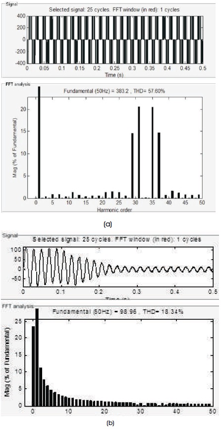
Figure 6. (a) THD in Inverter Voltage, (b) THD in Stator Current
Harmonics are displayed in percent of the fundamental component. As expected, harmonics occur around multiples of carrier frequency (n×33±k). Highest harmonics (30%) appear at 31th harmonic and 35th harmonic (33+2). It can be clearly seen in Figure 6(a). Note that the THD value for voltage is (57.60%) has been computed for maximum frequency 2500 Hz.
The harmonic analysis of stator current of the motor has also been done and shown in Figure 6(b). The THD in current has been observed 18.34% along with fundamental component 98.96 A.
After observing all waveforms, it can be deduced that the SVPWM inverter fed induction motor gives much better results as compared to SPWM inverter fed induction motor drives.
In this section, the authors have discussed performance comparison of SVPWM inverter fed induction motor drive and SPWM inverter fed induction motor drive. The SVPWM inverter control technique gives much better results with reduced harmonics as compared to SPWM inverter control method. Following conclusions have been made after observing results of SVPWM inverter control and SPWM inverter control. Same rating induction motor has been used for analysis purpose with SVPWM and SPWM control methods.
In this research paper, the SPWM inverter fed induction motor model and SVPWM inverter fed induction motor model were simulated in the latest MATLAB/Simulink environment. The performance analysis of the induction motor was achieved by both control techniques.
It was observed that the SVPWM inverter control technique fed induction motor drive gives much better results as compared to SPWM inverter control technique. A similar rating induction motor was used with both control techniques for clear comparison purposes.
It was also clearly observed that the SVPWM control technique produced less harmonics in the line to line voltage and increased fundamental output voltage by approximately 15% with smoother control of the induction motor.
To this end, a wider range of speed control may be achieved in a more efficient way. The SVPWM control technique used a reference vector for analysis purposes; the digital implementation produced a wide linear modulation range for output line-to-line voltage.
Therefore, due to these advantages, the SVPWM inverter fed induction motor technique could be used in industry in place of SPWM inverter fed induction motor drives, and be used in the future.