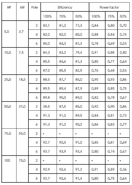
Table: 1 Efficiency and Power Factor of different Induction Motor at different Load
Efficiency: The efficiency of three-phase induction motor varies with type size and load. It ranges from 85% to 93% in case of squirrel cage motor above 5HP. It is about 75% in case of smaller motor. The efficiency is less in case of slipring motors; slow speed motors and motors running at part loads.
Motor losses can be classified in three categories
1. Iron loss
2. Rotational losses (friction and windage)
3. Ohmic losses
Among first two are constant losses, which is not affected by motor shaft load is known as constant losses. The third is the variable losses, which varies with motor shaft load and proportional to square of fraction of rated load. The efficiency of motor is decreases faster when load is below the 75% of rated load.
Maximum demand: In industries maximum demand is very important factor. The maximum demand depends upon the type of load. i.e. whether resistive or inductive load.
In industries, maximum electricity load is contributed by induction motor and it is highly inductive load., that's why the maximum demand varies much motor, depends on shaft load of motor and efficiency because it shaft load is lower than full load of motor. The power factor and efficiency of motor decreases and maximum demand is increases. . So that proper size of the motor selection will reduce the maximum demand and cut the electric bill. Energy saving: If motor is loaded above 75% of full load, motor has high efficiency but under load condition the efficiency reduces and increases the losses.
No Load current: No load current of induction motor varies from 25% to 60% of full load current. Usually no load power factor of induction motor is around 0.15 lagging or even less. No load current of some typical induction motor shown in table 2 for 2, 4 and 6 poles. Generally as the number of poles increases in induction motor the no load current of motor also increases, and at the same time full load current of motor also increases simultaneously. This can visualize from table 2 that motor no load current varies from 25% to 40% of full load current for 2 poles motors, 30% to 50% for 4pole motors, and 35% to 60% for 6 poles motors except some small capacity motors generally has higher values.
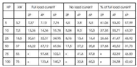
Table: 2 Line Current of Induction Motor at different load
Load current: To estimate the load current at different loads, we can use the information given in the manufacturer catalogues
1) Efficiency of motor at 100%, 75%, 50% of full load
2) PF of motor at 100%, 75%, 50% of full load.
3) Motor full load current.
To determine the load current at 100%, 75%, 50%, of full load, following formula is used

No load current may be determined by either no load test of motor or from motor test certificate. This graph can be utilize for determine the shaft load for given value of motor current.
III MOTOR LOAD ESTIMATION TECHNIQUES
Operating efficiency and motor load values must be assumed or based on field measurements and motor nameplate information. The motor load is typically derived from a motor's part-load input Kw measurements as compared to its full-load value (when kW or voltage, amperage, and power factor readings are available), from a voltage compensated amperage ratio, or from an operating speed to full-load slip relationship.
Kilowatt ratio Technique
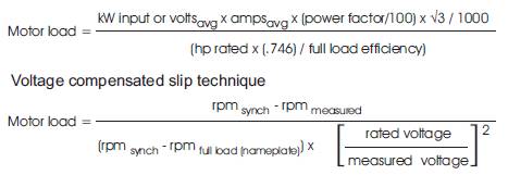
Also the slip technique as an indicator of load and suggests that loads be estimated by comparing a motor's true root-mean-square (rms) amperage draw against its full-load or nameplate value. Thus, the load on a motor is defined as:
Amperage ratio technique
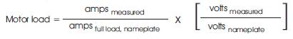
While the amperage of a motor is approximately linear down to 50% load, the relationship is not directly proportional (i.e., at 50% load, current is higher than 50% of full-load current). An improved version of the amperage ratio load estimation technique makes use of a linear interpolation between a motor's full- and half-load current values. The modified equation, useful for estimating loads in the 50% to full-load range, is:
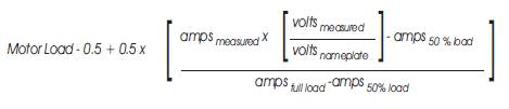
The current at 50% load (amps50%) can be found from manufacturer data or Motor Master.
IV AC VOLTAGE REGULATORS
Figure 1 shows the power circuit diagram of a singlephase half wave a.c voltage regulator using one thyristor in antiparallel with in diode. For three phase motors, three sets of single phase voltage controller to be used. Delaying the firing angle of thyristor T1 controls the power flow to the load. Due to the presence of diode D1, the control voltage is limited and the effective RMS output voltage can only be varied between 70.7% and 100% which is more than enough in this research (see Table no. 7). It can be observed from figure 1 that positive half cycle is not identical with negative half cycle for both voltage and current waveforms. As a result dc component is introduced in the supply and load circuits, which is undesirable. Since the power flow is control during the positive half cycle of the input cycle, this type of controller is also known as a unidirectional controller.
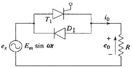
Figure 1 Single Phase Half Wave AC Regulator
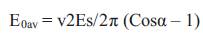
The average value of output voltage is given by,
V EXPERIMENTAL STUDY
Rating of the motor: 1 Hp, 1470 rpm, 1.9A, 3 phase, class E, 50 Hz, Delta connected Induction Motor
Table 3 No Load Test
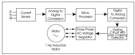
Figure 2 Block Diagram of Experimental Setup
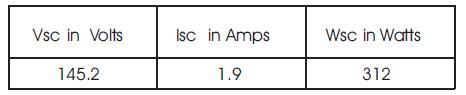
Table 4 Blocked rotor test
From the no load and load test we have found the following equivalent circuit parameters of the induction motor,

Table 7 shows the required voltage for different loading condition of the above motor. For example, consider the load current 1.3A. In this load, copper loss is 146W (from table5) and the same core loss occurred at 355V (from table 4). Since the maximum efficiency only occurred at copper loss = core loss, I have selected 355V as an optimum voltage to this load
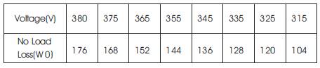
Table 5 No load loss Vs voltage
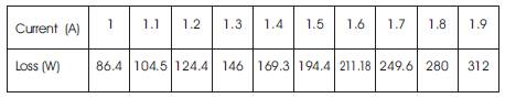
Table 6 Copper loss Vs line current
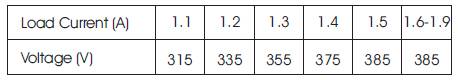
Table 7 Proposed Load Current Vs Voltage
VI CASE STUDY
Voltage control of lightly loaded induction motors should be judiciously planned based on the actual duty cycle. Case study where the energy conservation is applied in partial loaded induction motor in the organization (M/s SCM Textile spinners, Coimbatore, India) has been presented below
While carrying out the preliminary energy audit in 55 KW motor in spinning frame this motor, its load factor for one complete cycle is shown in table 8.

Table 8 Load factor for one complete cycle
Replacement of existing motor's starter by energy efficient drive (power electronics based voltage control) was recommended so as to improve the efficiency and power factor in the considerable amount.
VII Conclusion
In order to avoid harmonic current amplification due to power electronics load detuned filter circuits must be used. The demand-supply gap is expected to reach 1, 00,000MW by the year 2012 has been estimated in India. This will cause frequent power failures and cuts causing disruption in production, services and public life. Adoption of energy conservation measures is necessary to reduce effective demand. This would not only save huge investments required in building new capacity, but would also help in abatement of greenhouse gasses and other environmental pollutants