Figure 1. (a) Optical image of as cast material at optimum condition
In this research work, Fatigue Crack Growth [FCG] characteristics are studied using axial fatigue test on Compact Tension [CT] specimen for as cast, heat treated and welded material. The relation ship between fatigue crack growth rate and stress intensity factor range for crack growth are analyzed. How ever, the results of da/dN-ΔK curves for CT specimens and Paris constants are determined. The heat treated specimen shows lower growth rate compared to as cost and welded materials. The fracture surfaces of the tested specimen are observed under a scanning electron microscope to understand the type of fracture. The fracture mode is observed as quasi cleavage.
Magnesium alloys are extremely useful structural materials for aircraft industries, because of their higher specific strength compared with other metals and alloys [1-3 ]. Majority of magnesium alloy structural components is produced by casting processes such as sand casting, gravity die casting (permanent mold casting), squeeze casting, die casting [4-6 ]. The advantages in the metal-casting process are the near net-shape production leading to a reduction in additional fabricating processes, and the production of complex shape in one shot reduces number of assembled parts [7-8 ]. Magnesium casting will contain minimal microporosity and the tendency to hot cracking is low [9 ]. Heat treatment is an emerging process which to produce a cast magnesium alloy with improved ductility and strength significantly [10 ].
The welding of magnesium alloys by gas tungsten-arc (GTA), laser and laser-GTA hybrid welding have been investigated widely. For the advantages of utility and economy, GTA welding has been used extensively and the results on GTA welding have been reported [11 ].
The increased use of the alloy in various fields' demands knowledge about the fatigue properties of the alloy and the influence of microstructure on it as well. Eifler et al. [12 ] investigated the fatigue behaviour of the magnesium alloy AZ91D under constant and linearly increasing amplitude loading by means of mechanical hysteresis and temperature measurement reported that stress amplitudes above the endurance limit lead to cyclic hardening. Eisenmeier et al. [13 ] studied the strong influence of several micro structural features on the initiation and propagation of fatigue cracks and stated that crack propagation occurs mainly by the coalescence of smaller cracks.
In the present study, axial fatigue tests have been performed using CT specimens of ZE41A Mg alloy in as cast, heat treated and welded conditions. FCG characteristic are evaluated and the results of da/dN-∆K curves for CT specimens and Paris constants are determined. The fracture surfaces of the tested specimen are observed to understand the type of fracture.
The sand-cast ZE41A magnesium alloy is composed of 3.5-5 wt % Zn, 0.8-1.7 wt % RE, 0.4-1 wt % Zr and remaining wt% as magnesium. The cast alloy is supplied by Hindustan Aeronautical Limited, Bangalore, India. The test is carried out in as cast, heat treated and welded conditions. For as cast alloy, fatigue test specimens are machined from as received cast billet with the tensile axis parallel to the casting direction. For as heat treated metal, the alloy is heat treated in a muffle furnace by the solutioning at a temperature of 3300C for 2hrs to improve the strength and gives toughness and shock resistance. Artificial ageing is performed after solutioning treatment of magnesium alloy at 1800C for 16hrs, to improve hardness and strength [14].
The welded samples is obtained by welding the as cast billet of 100 x 50 x 18 mm. GTAW process with arc current of 200 amp, filler metal diameter of 4 mm and argon gas flow rate of 19 lit/min are employed. The filler metal of same base metal composition is used and leftward welding technique is followed and a preheat temperature of 200 0C is maintained. After the completion of the welding process, the welded plate is heat treated by solutionizing at a temperature of 330 0C for 2 hrs to improve the strength and shock resistance of the alloy followed by ageing was done at 180 0C for 16 hrs to improve hardness and strength [15 ].
For metallographic observation, samples are cut from the as cast, heat treated and welded plates. The specimen are first polished with silicon carbide sheet paper of 600-2000 grade and subsequently mechanically polished with 1µm diamond oil suspension. After polishing, the structure is revealed by nital solution (5 ml HNO3 (conc.), 95 ml Methanol) is used as the echants and briefly applied to the surface of samples which are then thoroughly rinsed with water and dried [16 ].
Fatigue crack growth test are performed on compact tension specimens which are machined from as cast, heat treated and welded plates as per ASTM standard (E647) having 32 mm width and 16 mm thickness [17 ]. In welded metals the notch is machined on nugget direction. The electro servo hydraulic fatigue testing machine operating under a load ratio R= 0.1, frequency of 10 Hz at ambient temperature. The crack length is measured with a clip gauge or extensometer. After testing the fractured specimens are examined using JEOL Scanning Electron Microscope (SEM).
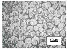
The initial microstructures of the as cast, heat treated and welded materials are characterized by optical microscopy. Figure 1 (a) shows that the average grain size of cast material are about 44 µm. The edges are not sharp and the grain boundaries are uneven. The microstructure displays evidence of porosity and fragmented grains.
Heat treatment, however, refines the grains. The grains are evenly distributed, but nevertheless, few grains are found broken. The heat treated metal shows the average grain size of about 38 µm and the grains are uniformly distributed with near spherical shape. Heat treatment, it appears, has reduced the initial porosity with the interfacial integrity good. Figure 1 (b) exhibits that on solid solution heat treatment of parent metal, the network largely breaks down into separate fragments. As stated, the excess β will be dissolved and the structure will be a homogeneous solid solution. So that mg solid solution becomes the continuous phase.
Figure 1. (a) Optical image of as cast material at optimum condition
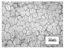
Figure 1. (b) Optical image of heat treated material at optimum condition
This quaternary alloy contains zirconium and rare earth metals which plays vital role to achieve better properties. In this alloy, zirconium compound is separated from the liquid above the peritectic temperatures. This undergoes a peritectic reaction resulting in grain refinement. Zirconium addition completely eliminates the coarse grained, columnar cast structure, thus increasing the mechanical properties [18 ]. The addition of rare earth metal reduces micro porosity, hot crack and increases the strength and creep properties [19 ]. The compound network in the grain boundaries consists of one phase as divorced eutectic, so that it presumably contains both zinc and rare earth metals in addition to magnesium.
Figure 1 (c) shows that average grain size of weld metal are about 40.5 µm. All welded metal leads to grain refinement compared to initial structure due to post treatment. A clear and well defined boundary is seen existing between the fusion zone and the heat affected zone. In fusion zone the edges of the grains are not well defined and the boundaries are hazy. Large numbers of particles are precipitated in the network largely which breaks down the grain into separate fragments in fusion zone.
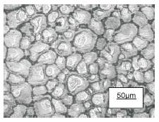
Figure 1. (c) Optical image of fusion zone of welded material after heat treated at optimum condition
A fatigue fracture always starts as a small crack under repeated loading of the stress. The event that leads to fatigue crack growth includes crack nucleation, crack growth and fracture. The crack growth rate is determined from either by graphical procedures or by computation. The most significant of crack becomes longer at an increasing stress level, thereby shortening component life at an alarming rate.
The changes in the grain refinement and grain structure are shown in Figure 1 vary the fatigue crack growth of the materials. The crack nucleation and propagation for this alloy [20 ] are mostly of intergranular type particularly because of poor cohesive strength between the grains. In welded material large numbers of particles are precipitated in the network which breaks down the grain into small fragments in fusion zone. This emerges higher rate of crack growth in comparison to as cast and heat treated material.
The relationship between the crack length and number of cycles is shown in Figure 2. The results articulate that fatigue crack nucleates in the early stage of life for as cast, heat treated and welded materials. The rate of crack nucleation's for the heat treated was lower compared to as cast material and welded material. Figure 3 shows the relationship between fatigue crack growth rate and crack length. The results shows that welded material have higher fatigue crack growth rates compared to the as cast and heat treated material. Moreover, the rate crack growth becomes higher with increasing crack length. The relation ship between crack growth rate, da/dN and ∆K is represented in the Figure 4. From the figure, it is found that the threshold value for as cast, heat treated and welded material of ∆K is 2.05, 2.37and 1.47 MPa√m. The Paris law constant A and B from the Eqn. (1) of as cast material are 6.97x10⁻⁸ and 3.202, for heat treated are 5.296 x10⁻⁷ and 2.084 and for welded material are 2.245 x10⁻⁵ and 1.398 respectively.
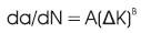
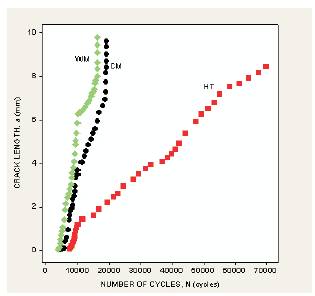
Figure 2. Relationship between crack length and number of cycles of as cast heat treated and welded material.
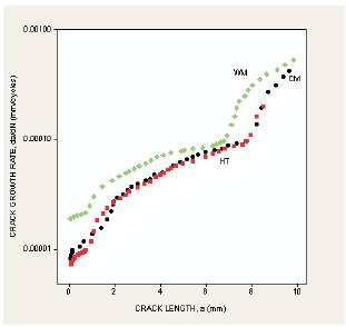
Figure 3. Relationship between crack growth rate and crack length of as cast, heat treated and welded material.

Figure 4. Relationship between crack growth rate and stress intensity factor of as cast, heat treated and welded material.
The fatigue growth curve for the welded material demonstrates lower fatigue crack growth resistance compared to as cast and heat treated material. However, the difference of crack growth resistance becomes smaller with increasing factor range ∆K and almost diminishes at ∆K values above 1.0 MPa√m. Fatigue crack growth characteristics is shown by the change of slope in the curves (Figure 4) occur for a ∆K of 3.05 MPa√m for as cast, 3.86 MPa√m for heat treated and of 2.68 MPa√m for the welded material.
The transition of fracture mechanism from slip deformation to quasi cleavage fracture occurs when the cyclic plastic zone size is equal to the average grain size. When plastic zone is less than the grain size a fatigue crack will propagate along the most active slip plane with out multiple slip deformation. The cyclic plastic zone size rcp, for plain strain state is obtained by the Eqn. (2)
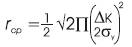
Where σy = 138 MPa for cast material, σy = 140 MPa for heat treated material,
σy = 132 MPa for welded material.
Considering the effect of closure, effective stress intensity factor range ∆Keff is calculated using Eqn. (3).

Where
SR = Stress ratio
The resultant crack growth is shown in Figure 5. From the figure, it is observed that all fatigue crack growth curves are closer to each other. The threshold effective stress intensity factor range is around 1.1 MPa√m for as cast material, 1.27 MPa√m for heat treated material and 0.8 MPa√m for welded material. It emphasizes that the difference in crack growth resistance and threshold stress intensity factor range are mainly due to the difference in crack closure behaviors of specimen's material.
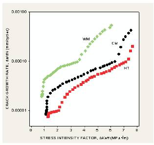
Figure 5. Relationship between crack growth rate and effective stress intensity factor of as cast, heat treated and welded material.
From the fatigue test results, it is articulated that the higher critical stress required for fatigue crack nucleation in the as heat treated material compared to as cast and welded material. The higher threshold stress intensity factor and fatigue crack growth resistance in the as heat treated material may also be attributed to the higher fatigue limit.
Figure 6 (a), (b) and (c) reveals the typical samples of SEM micrographs showing fracture surface appearance. Figure 6 (a) shows some plastic deformation with secondary cracks and the fracture mode is observed as quasi cleavage. The crack growth is observed in the direction perpendicular to tensile load. Figure 6 (b) exhibits some plastic deformation with cracks. The cracks formed are not continuous one. The fracture surface denotes as quasi cleavage. Figure 6 (c) shows cracks and more voids on the fracture surface, this tends to make quasi cleavage. The cracks are discontinuous in formation. In all cases the crack develops from left to right side. It has been argued that the formation of large number of voids in welded material increases the growth rate while compared with other two cases. Similar observation was made by Wang et al. [22] for AZ61 magnesium alloy.
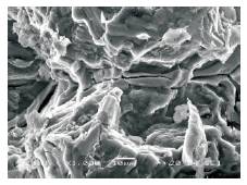
Figure 6 (a). SEM of fracture surface of as cast material
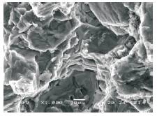
Figure 6 (b). SEM of fracture surface of heat treated material
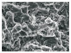
Figure 6 (c). SEM of fracture surface of welded material
The authors are grateful to the Department of Forging and Foundry Division, Hindustan Aeronautical Limited, Bangalore, for providing Magnesium alloy material for carrying out the work.