Figure 1. Proposed Configuration
Nowadays researchers are focussing on compact system design for all engineering applications without sacrificing the system performance. This paper deals with the importance of micro electro mechanical systems and its usage in day-today life. One such mechanical component is mechanical pump, which is used in various sectors of industrial, household and medical systems. This work is concentrated on Piezo-driven valve-less micro pump, which does not have check valves. The fluid flow direction is controlled by converging and diverging nozzles. Thermo Electro Mechanical Analysis is done to evaluate mechanical (stress, force, pressure, acceleration, piezoelectric), thermal (temperature, convection, heat flux, resistive heatingincluding variable resistors and Piezo resistors) and Electrical (capacitive forces defined by voltages) properties.
Micro fluidic components fabricated using micromachining technology, has the advantage over conventional machining process. A valve - less pump which uses the flow directing effect of diffuser elements is presented in this work. One of the main advantages of the pump is the absence of moving parts, except the pump diaphragms, which reduces the risk of mechanical failure.
The pump utilizes the reciprocating motion of a diaphragm actuated by a piezoelectric disk, to induce pumping action. The diffuser and nozzle section is used to direct the flow. The micro pump design process involve the following three steps.
| i. | Diaphragm design |
| ii. | Diffuser\nozzle element design |
| Iii. | selection of suitable Piezo-actuator |
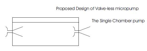
A survey through the literature, focuses on the single chamber silicon micro pump (Figure 1). It consists of diffuser/nozzle element, Piezo-di sc actuat ion mechanism, silicon membrane, and glass packaging.
Figure 2 and Figure 3 show Wire frame model and 3D view of the micro pump. The model was developed using Solid works software. The micro pump consists of Piezo Actuator, Diffuser Elements, Silicon Membrane and Input / Output Ports.
Figure 1. Proposed Configuration
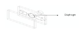
Figure 2. Wire frame model of micro pump
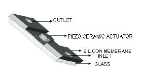
Figure 3. 3D view of micro pump
Modeling the pump diaphragm - Piezo disc bimorph implemented in this design is not straightforward because the pump diaphragm itself is clamped at its circumference only one side. There is also a difference in diameter between the Piezo disc and the pump diaphragm.
The analytical formula for the diaphragm deformation is given as,
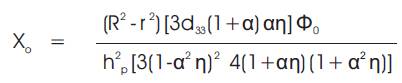
Where, η = S11 x E (1- ν2p )/ (1- ν2m ), á = R/r, R = Radius of silicon chamber, r = Radius of Piezo-disk, d33 = Piezo electric charge constant, Ф0 = voltage over the Piezo disc, hp = Piezo disk thickness, s11 = Elastic compliance, E = Young's modulus of the diaphragm material, νm = Mean flow velocity.
This formula describes the static deflection of the bimorph structure under a certain driving voltage. It does not describe the dynamic behavior of the pump diaphragm, nor does it take into account any fluid forces from inside the pump chamber. Nevertheless, it relays information about the diaphragm and Piezo disc thickness and the preferred diaphragm material. A graph of the calculated maximal centre deflection of the diaphragm Piezo disc bimorph as a function of á is shown in Figure 4. When using discrete glued-on Piezo disc elements with a standard thickness, this model indicates optimal diaphragm thickness. For a 0.25mm thick Piezo disc, a silicon diaphragm thickness of 0.034 mm is predicted to be optimal.
Finally, the Diaphragm thickness would be 0.034 mm optimized from the graph (Figure 4) using the above equation 1.
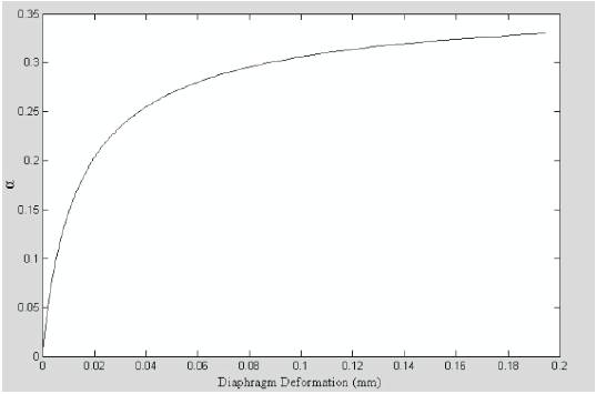
Figure 4. Variation of Diaphragm deformation with respect to α.
The key element in the diffuser pump is the diffuser element. A diffuser is a gradually expanding flow channel intended to raise the static pressure. The largest pressure rise is achieved for small opening angles. The diffuser element is a diffuser with a rounded inlet and a sharp outlet. It is characterized by a lower flow resistance in the diffuser direction than in the opposite direction, the nozzle direction. In the valve-less diffuser pump diffuser elements are used as flow directing elements. One diffuser element is directed from the inlet chamber to the pump chamber and the other diffuser element from the pump chamber to the outlet chamber. A moving boundary of the pump chamber forces the fluid through the two diffuser elements. The result is a net transport of fluid from the inlet side to the outlet side due to the difference in the flow resistances in the diffuser and nozzle directions.
The basic element in the diffuser pump unit consists of two diffuser elements connected to a fluid cavity volume with an oscillating diaphragm as shown schematically in Figure 5. The pump operation is based on the flow directing properties of the two diffuser elements. With correctly designed diffuser elements more fluid flows through the inlet element than through the outlet element during the supply mode. During the pump mode more fluid flows through the outlet element than through the inlet element. This results in a net flow from the inlet side to the outlet side of the pump unit.
To optimize the efficiency of the diffuser element ratio should be maximized. To achieve this entrance region of the diffuser in Figure 6 should be rounded. As shown above the part with expanding cross-section shows best performance with an opening angle θ of about 44o. The outlet should be sharp. Using pressure loss coefficients for macroscopic flows this gives a maximum diffuser element efficiency of 3.6.
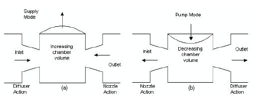
Figure 5. Working modes of diffuser\nozzle sections
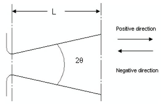
Figure 6. Diffuser element geometry
The Diffuser element efficiency [1] can be written as

η= Diffuser/Nozzle element efficiency
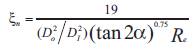
The Flow resistance coefficient of the Diffuser Element [1] can be written as
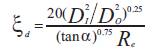
| ξd | = | Flow resistance coefficient of the Diffuser |
| Dl | = | Inlet diameter of diffuser |
| D0 | = | Outlet diameter of the diffuser |
| α | = | Conical angle of diffuser |
| Re | = | Reynolds number |
The Flow resistance coefficient of the Nozzle Element [1] can be written as
| ξn | = | Flow resistance coefficient of the Nozzle |
| D1 | = | Inlet diameter of Nozzle |
| D0 | = | Outlet diameter of the Nozzle |
| α | = | Conical angle of Nozzle |
| Re | = | Reynolds number |
Where,

| v | = | Mean flow velocity |
| d | = | Diffuser inlet width |
| y | = | Kinematic viscosity |
The Flow Rate [1] can be written as
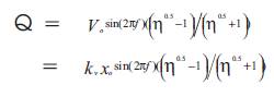
| Q | = | Flow rate |
| V0 | = | Volumetric Displacement. |
| f | = | Applied frequency. |
| x0 | = | Chamber displacement. |
| Kv | = | constant |
| η | = | Diffuser/Nozzle element efficiency. |
| Silicon wafer dimensions | 27 x 22 x 0.35mm |
| Chamber diameter | 10 mm |
| Chamber depth | 0.20 mm |
| Nozzle max diameter | 0.29 mm |
| Nozzle minimum diameter | 0.15 mm |
| Diaphragm material | silicon |
| Diaphragm diameter | 10mm |
| Diaphragm Young's modulus | 160 Gpa |
| Diaphragm thickness | 0.034mm |
| Nozzle/diffuser angle | 440 |
| Flow rate | 7.8μl\s |
| Type of actuation | Piezo -Disk Bender |
| Material | Piezo ceramic |
| Piezo electric constant | 370 x 10-12 m/V |
| Piezo electric device diameter | 8 mm |
| Piezo electric device thickness | 0.25 mm |
| Piezo electric Young's modulus | 6.6 x 10⁶ Pa |
| Poisson's Ratio | 1 0.33 |
| Voltage range | 50 150 V |
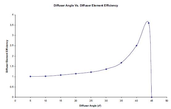
Figure 7. Diffuser\nozzle angle VS diffuser\nozzle element efficiency
The technology is based on the use of SOI (Silicon on Insulator) wafer; silicon etching and the sacrificial etch of the buried oxide layer in order to release the structures. This approach brings several major advantages over the more traditional silicon bulk micromachining techniques,
| i. | It permits the design of an original inlet valve (patent pending) optimal in terms of dead volume and process compatibility with the other elements of the pump. |
| ii. | It represents a major simplification of the process and brings additional design freedom. As a comparison, this process only requires 8 etch steps in silicon wafer and a total of 3 masks while the process of membrane required 6 different levels. |
| iii. | It achieves a very good control over the thickness of the membranes and fluidic channels thanks to the well defined SOI thickness and the etch stop oxide layer, leading to well defined mechanical characteristics. The membranes of the different elements are located on the same side of the wafer and the dead volume is minimized. |
| iv. | The deep etch with vertical walls of the backside allow high aspect ratio structure and channels and the placement of the different elements in close proximity. It also allows small size circular membranes. As a result, the whole pump becomes very compact. The required mask layout was developed by using IntelliMask module in the Intellisuite software. This fabrication sequence was constructed and simulation was verified with the Intellisuite software. |
The silicon membrane and the glass structure are bonded by using Pyrex anodic bonding in the IntelliFab module. Figure 8 shows the full assembled view of the micro pump. The static deflection of membrane is calculated using Thermo Electro Mechanical analysis module (Figure 9) in the Intellisuite software.

Figure 8. Assembled view of micro pump
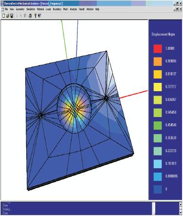
Figure 9. Static deflection of membrane is analyzed using Intellisuite software
The various analyses present in the previous chapter is used to check the important design parameters such as the diffuser\nozzle diameter, the diaphragm thickness, Piezo-actuator specifications, etc. The natural frequency of the Piezo actuation is one of the most important parameters in the design of valve-less pumps since the best performance occurs at that frequency. Figure 10 shows the flow rate as a function of the driving frequency for optimal dimensional values of micro pump. From the graph the highest flow rate is obtained at the frequency of 72Hz. As also expected, flow rate increases for increasing the frequency of Piezo actuation till 72Hz, and then flow rate decreases with increase of frequency of the Piezoactuation. At the natural frequency of the Piezo actuation (72Hz) and known volume displacement of the membrane the flow rate is 7.8μl\sec. The present analysis is aimed at improving our understanding of the Piezoelectric pumping functions and the design capability for a pump assembly. Obviously, for a proper design, the input variables such frequency, loss coefficient, volumetric displacement, etc., should be known for any specific piezoelectric actuator and controller part.
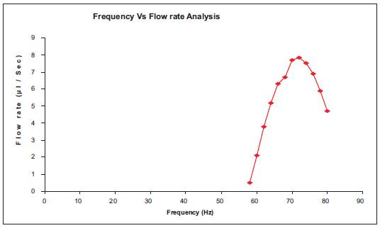
Figure 10. Variation of flow rate for various frequency of Piezo disc
The model provides the flow rate of a pump actuated by Piezo electricity at a given frequency of Piezo - actuation and diffuser\nozzle element efficiency. Pumps have been fabricated using different fabrication methods and materials. The fabrication process of this micro pump was simulated using Intellisuite software. Due to the lack of moving parts one can expect advantages of the new pump principle such as simplicity, robustness and high reliability. The new pump principle described in this project is general and has many potential applications, not only in micro pump applications. The uncomplicated structure facilities low fabrication costs. The absence of moving parts makes it possible to pump many different types of fluids such as gases, liquids and fluids with solid particle contents with reduced risk of clogging. Furthermore, the new pump principle is believed to be gentler to sensitive fluids than, e.g. pumps with passive check valves.