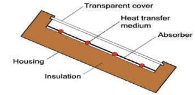
Figure 1. Flat Plate Solar Collector
Solar Energy is the major source of energy, and utilization of it requires solar collectors. A device generally called solar concentrator is used. Concentration of solar energy can be done by using either reflecting or refracting elements, which are so positioned that, solar flux is directed on the absorber. With the help of a flat plate collector, it is possible to get emperature around 100oC to heat liquids or gasses. There are several processes operating at much above 100oC, where high energy is required. This can be achieved by using concentrating collectors. Solar parabolic trough collector is currently used for the generation of electricity and applications with relatively higher temperatures. Parabolic trough collectors are typically operated at temperatures above 250 oC. An attempt is made in this project to develop a parabolic trough collector for water heating more effectively as compared to the flat plate collector. Thermal analysis procedure of a solar parabolic trough collector design starts with the selection of certain parameters such as aperture area and diameter of receiver to obtain the geometric concentration. In this investigation, experimentation is based on varying concentration. An experimental parabolic trough collector with aperture 1.2 m, focal height 0.3 m and trough length 3 m is constructed. A G.I pipe having inner diameter of 25.4 mm and outer diameter of 28 mm placed at the focal axis is used as receiver.
Energy is an essential element for our livelihood and for the advancement of human kind. Yet the word ‘energy’ comes from the Greek, (in) and ergon (work). Energy plays a key role in economic development, due to the utilization of energy appropriately.
Of all the various types of energy resources that are used today, hydrocarbons are the predominant hydropower atomic energy. Solar energy is the salient source of energy. The other sources of energy are listed as follows.
Energy Resources which have been traditionally used for many decades, and were in common use around oil crisis of 1973, are called conventional energy resources. Ex: Fossil fuels, Nuclear and Hydro resources.
Energy resources which are considered for longs scale use after the oil crisis of 1973 are called non-conventional energy resources, ex: Solar, Wind, Biomass etc.
Resources which are finite and do not get replenished after their consumption are called non-renewable resources.
Resource, which are renewed by nature again and again, where their supply is not affected by the rate of their consumption are called renewable resources. Ex: Solar, Wind, Biomass, Ocean, Geothermal, Hydro etc.
The most abundant energy source available to the human race is the solar energy-specification. Electromagnetic energy is emitted by the sun. While solar energy is not being used as a primary source of fuel energy at the present time, a large research and development effort is underway to develop economical systems to harness solar energy as a major source of fuel energy, particularly for the heating and cooling of buildings.
Solar energy is the primary source of energy for our planet. The average solar energy reaching the earth in the tropical zone is about 1 kwh/m2 and total radiation for a day is at the best for about 7 kwh/ m2 . The solar constant Isc is the rate at which energy is received from the sun on a unit area perpendicular to the rays of the sun, and at the mean distance of the earth from the sun, the value of Isc is 1353 w/m2 . Increased utilization of solar energy in our country would result in all around benefits, both in terms of cleaner environment and monetary gain. The energy from the sun is used for various purposes mainly as power generation known as solar electricity generation system and industrial process heat applications [1].
The energy consumption in residential sector is substantial as it accounts for approximately one-third of overall delivered-energy use and carbon dioxide emissions of this delivered-energy use, approximately a quarter is for water heating. Water heating is generally provided by burning non-commercial fuels, namely-firewood as in rural areas and for this application rural people are cutting trees to partially fulfill of their daily energy requirements. This creates depletion of forests, and thus it has an effect on climate change and commercial fuels such as kerosene oil, Liquefied Petroleum Gas (LPG), coal; through either their direct combustion or through the use of electricity in urban areas [2]. The uses of fossil fuels create air pollution and the costs of natural resource depletion. In our country, use of solar trough is mainly for power generation, industrial process heat applications, and for this application development in the commercial industry, to produce and market these solar trough systems, it's time to use the solar trough for domestic applications and also manufacture it using the locally available materials.
Sagade et.al, conducted the experiment on parabolic trough made of Fiberglass-Reinforced Plastic (FRP) with its aperture area coated by aluminum foil with a reflectivity of 0.86. This line-focusing parabolic trough with mild steel receiver has been tested with and without glass cover. From Indian conditions, low-cost FRP parabolic trough system proves to be beneficial for industrial heating applications as well as domestic heating [3].
Valan Arasu and Sornakumar explained the design and manufacturing of smooth 90°-rim angle fiber glassreinforced parabolic trough for water heating applications. The total thickness of the parabolic trough is 7 mm. The concave surface where the reflector is fixed is manufactured to a high degree of surface finish. They have found that, the standard deviation of the distribution of the parabolic surface errors is 0.0066 radians from the collector performance test according to ASHRAE Standard 93 (1986), which indicates the high accuracy of the parabolic surface [4].
Ruby et.al, performed through the design, construction, operation, and analysis of a high temperature solar thermal system at a Frito-Lay snack food plant located in Modesto, California. In this installation, high temperature water is produced by a concentrating solar field, which in turn is used to produce approximately 300 pounds per square inch (20 bar) of process steam. Process steam in the plant is used for cooking, which includes heating edible oil for frying, and heating baking equipments. Steam is also converted into hot water for cleaning and sterilization processes [5].
Ming Qu et.al developed the linear tracking parabolic trough reflector focused on a surface-treated metallic pipe receiver enclosed in an evacuated transparent tube, and obtained the fundamental radiative and convective heat transfer and also mass and energy balance relations. The experiment shows that, when hotwater at 165 °C flows through a 6 m by 2.3 m parabolic 2 trough solar collector with 900 w/m solar insulation and 0 incident angles, the estimated collector efficiency is about 55% [6].
Brooks, M.J. et.al, conducted an experiment to measure and test the performance of components of parabolic trough solar collector and to create a development in a solar energy research programme. Low-temperature testing was performed at Mangosuthu Technikon's STAR lab facility using water as the working fluid. Both an evacuated glass shielded receiver and an unshielded receiver were tested, with which peak thermal efficiencies of 53.8% and 55.2% were obtained respectively. The glass-shielded element offered superior performance at the maximum test temperature, and the experiment also contain the tracking system. Pumping system is provided for feed control quantity of fluid. In this study, only lowtemperature testing was conducted with receiver inlet temperatures from 20 °C to 85 °C [7].
In the present work, new parabolic trough collector system with manual tracking system has been developed for hot water generation, fabrication and the design of a solar parabolic trough is done using locally available materials. The great advantage of solar trough is that, it is clean, cheaper and can supply thermal energy without any environmental pollution. Therefore it directly substitutes renewable energy for fossil-fuels, non-commercial fuel namely- firewood and also helps to cut utility electricity bills. At rural level and remote areas, this system can be used for hot water generation, crop drying, laundries, dairy, food preparation and service facilities. Hence low temperature trough will be a better solar thermal device for the rural area.
A solar collector is a device designed to absorb incident solar radiation and to transfer the energy to a fluid passing in contact with it. Solar collectors can be classified in to two types according to their collecting characteristics.
(1) Non-concentrating (or) flat plate collectors.
(2) Concentrating (or) focusing collectors.
A flat plate collector basically consists of flat surfaces, with absorptive for solar radiation, called the absorbing surface. The important parts of a typical liquid heating flat plate solar collector is shown in Figure 1.
Figure 1. Flat Plate Solar Collector
For many applications, it is desirable to deliver energy at temperatures higher than those possible with an ordinary flat plate's collection. Energy delivery temperatures can be increased by decreasing the area of the absorber from which heat losses occur. This is done by interposing an optical device between the source of radiation and the energy-absorbing surface, to raise the level of incident radiation on relatively small absorber. Concentrators can have concentration ratios from low values of 1.5 to high values of order 10,000.
Concentrating collectors are of various types and can be classified in many ways. They can be reflectors or refractors. They can be cylindrical to focus on a line or circular to focus on a point. Receivers can be concave, flat or convex in shape. They may be continuous or segmented. Line focusing collectors shown in Figure 2 usually have concentrations ratios between 10 and 30 and yield temperatures between 150oC- 300oC.
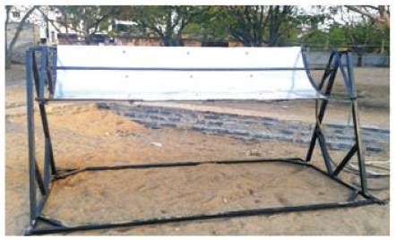
Figure 2. Line Focusing Collectors
The most common definition of concentration ratio 'c' (area concentration ratio) is the ratio of area of the aperture to the area of the receiver. C=Aa /Ar
This ratio has upper limit that depends on whether the concentration is of a three dimensional (circular) concentrator such as a parabolic, or of a two dimension (linear) concentrator such as cylindrical parabolic concentrator.
A parabolic trough is a type of solar thermal collector that is straight in one dimension and curved as a parabola in the other, lined with a polished metal mirror. A tube, frequently known as a Dewar tube, runs the length of the trough at its focal line. The mirror is oriented so that, the sunlight which it reflects is concentrated on the tube, which contains a fluid which is heated to a high temperature by the energy of the sunlight. The hot fluid is piped to equipment, such a heat engine, which uses its energy for some purpose like generating electricity. This solar energy collector is the most common and the best known type of parabolic trough.
From Figures 3 and 4, some convenient equations for parabolas are,

where f = the focal length of the parabola.
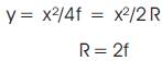
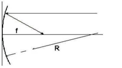
Figure 3. Measurement of Parabola Geometry-1
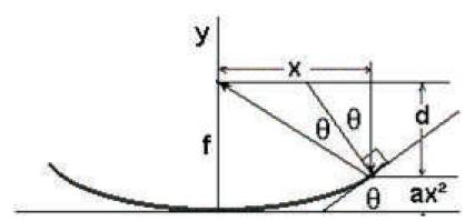
Figure 4. Measurement of Parabola Geometry-2
Proof for a Parabola focuses parallel rays of light to a Point. The general equation for a parabola is quadratic:

Calculus tells that the slope of such a curve is given by:

But we know that the slope is just the rise over the run, which is the same as the tangent. So

thus we have
tanΘ=2ax
Now tan2q=x/d. So the distance d = x/tan 2 and, by trigonometric relationship, tan 2q = 2tan q /(1-tan² q) Substituting from above tan q = 2ax, we have,
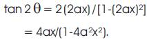
So, d = x (1-4a²x²) / 4ax = (1/4a) - ax².
Thus f = d+ax² = 1/4a and is invariant with x. Q.E.D. It also gives a convenient formula for a parabola: y = x² /4f.
Calculus tells us that for any curve, the radius of curvature of the curve at a particular point is given by
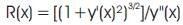
where y' = the first derivative at the point, and y" = the second derivative at the point.
For the parabola y(x) = x²/2f, the first derivative is: y'(x) = x/2f = x/R and the 2nd derivative is y"(x) = 1/2f = 1/R. Plugging this into the radius of curvature expression gives:

At the very center of the parabola, where x=0, we have R(0) = 2f = R Now, most telescope mirrors are shallow, so they have long focal lengths, and thus long radii of curvature. If we plug in the actual numbers, the radius of curvature of the outer edge is only slightly longer than the radius of curvature of the center. The calculated dimensions of the cylindrical parabolic trough are fixed as: Aperture width (w) =1.2 mails; Focal distance (f) =0.3m; Length of the parabolic trough (l) =3 mat the focal axis and we arrange the absorber tube which absorbs all the solar radiation rays. Figure 5 shows the Radius of Curvature of Concentric Collector.
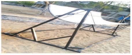
Figure 5. Radius of Curvature of Concentric Collector
In this, the construction details of the concentrator is presented and its operation has been described.
This unit consists of a polished aluminum sheet bent in the shape of the parabola where the concentrator has an aperture width1.2m, length 3m, focal height 30mm and curvature length of 1.54m. The aluminum sheet is held in shape by fixing 7 MS (Mass of Steam) flat plates using bolt and nuts, two on the front two on the back. The MS plates have the same curvature length as that of Cylindrical Parabola (CP). The longitudinal edges of the cylindrical parabola are attached with 2 MS flat plates on either side by spot welding. Two MS flat plates are bent to u-shap and are attached to the MS plates are welded to the V junction on either side. Two MS plates are taken and holes are drilled on them as to accommodate a 2 inch clamp so that focal or the extreme front ends of the cylindrical parabola by arc welding. The 2-ends of the V-plates are equidistant from the vertex of the CP (Specific Heat). Two solid Mass of Steam (MS) rods point lies at the centre of the clamp. Then these two MS plates are arc welded between the V junction and at a distance of 2.5 cm from vertex on either side of the C.P. Two hooks were welded at the middle of the longitudinal edges of the C.P. on either sides.
The absorber tube made of M.S. has an inner diameter of 25.4 and outer diameter of 28 mm. It is fitted to the reducers with 63 to 25mm for inlet side and 63 to 25 mm for outlet side. A gate valve is placed at the outer side.
The valve controls the flow rate of water through the pipe. This tube is placed at focal axis of the C.P. by clamping it to the MS plates on both ends of flexible rubber pipe (0.5 inch) connected to the inlet side reducer and another pipe (0.5 inch) connected to the outer side reducer. The inlet side flexible pipe is connected to the water supply. The entire length of the absorber is coated with black paint for effective results.
The collector is oriented with its local axis pointed to East- West or North-South direction. In East-West orientation, the axis is horizontal. While in North-South, the axis may be horizontal or inclined. The various tracking modes aregiven below. The focal axis is east-west and horizontal. The collector is rotated about a horizontal east-west axis and adjusted to one every day, so that the solar beam is normal to collector aperture plane at noon on that day. The same is adjusted continuously so that, the solar makes minimum angle of incidence with aperture plane at all time of day.
The solar cylindrical parabolic trough collector has aperture of 1.2m; length of the concentrator is 2.5m. The absorber made of G.I has an outside diameter 28mm and 25.4mm inner diameter. It is coated with a heat resistant black paint. The parabolic collector is oriented with its local axis pointed in the North-South direction and horizontal. The collector is rotated about the north-south axis and in adjusted continuously so that, the solar beam makes the minimum angle of incidence with the aperture plane at all time. By operating the control valve, the flow rate of the fluid to be heated is controlled. Experiments have been carried out for different flows, i.e., one particular flow throughout the day, by using thermometer at an interval of half an hour throughout the day. During the experimentation, the parabolic trough in rotated (not with constant angular velocity i.e., irregularly,) so that the image always falls on the absorber. Readings and results are presented in the form of tables and graphs.
From the Tables, (Tables 1-6) it shows that, as the time increases, outlet temperature of the flow first increases and decreases in the later afternoon.

Table 1. Proddatur Water Flow Rate:0.058kg/sec at YSR Engg. College, Date: 21-04-2013
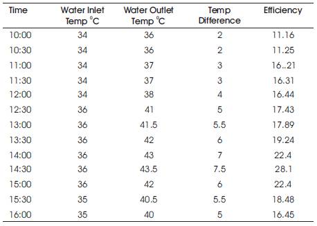
Table 2. Proddatur Water Flow Rate: 0.042 kg/sec at YSR Engg. College, Date: 22-04-2013
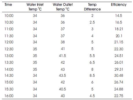
Table 3. Proddatur Water Flow Rate: 0.073 kg/sec at YSR Engg. College, Date: 23-04-2013
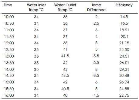
Table 4. Proddatur Water Flow Rate: 0.073 kg/sec at YSR Engg. College, Date: 24-04-2013
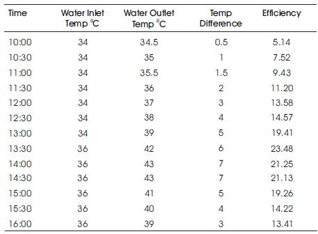
Table 5. Proddatur Water Flow Rate: 0.08 kg/sec at YSR Engg. College, Date: 25-04-2013
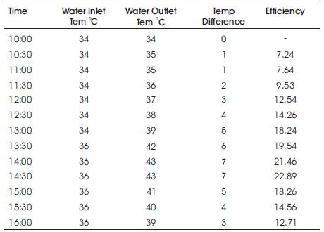
Table 6. Proddatur Water Flow Rate: 0.09 kg/sec at YSR Engg. College, Date: 27-04-2013
As the time of the day passes, the efficiency of absorber first increases and then decreases in the afternoon. As the mass flow rate increases, the efficiency of the absorber decreases.
Beam Radiation :
And the slope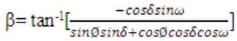
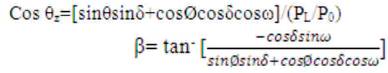
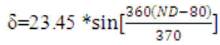
Beam radiation,
Diffuse radiation,
Beam radiation in direction of rays,
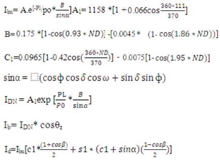
Reflectivity of aluminum foil,
s1=0.7Id =220.040w/mIg = Hourly beam
radiation = Ib +I dIg =1180.607 w/m
Now, Qw = Rate of useful heat gain = m.cp .t
Instantaneous collection efficiency,

Instantaneous efficiency (beam)
Figures 6,7,8,9,10 show the temperature difference and thermal efficiency with different flow rate in kg/sec.
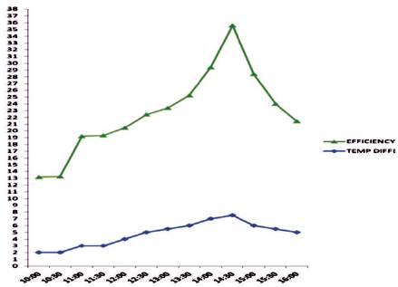
Figure 6. Temperature Difference and Thermal efficiency with Different Flow Rate 0.042 kg/sec
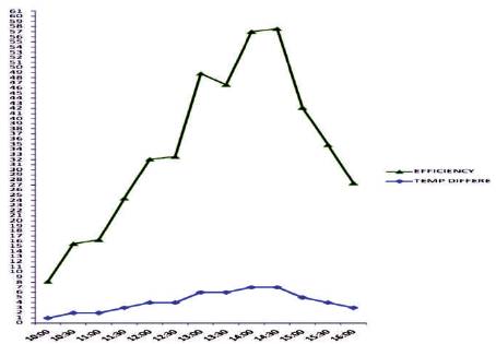
Figure 7. Temperature Difference and Thermal Efficiency with Different Flow Rate 0.058 kg/sec.
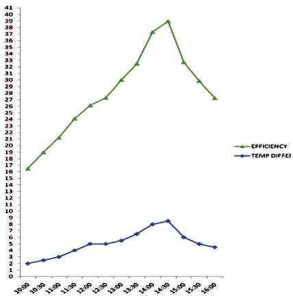
Figure 8. Temperature Difference and Thermal Efficiency with Different Flow Rate 0.073 kg/sec
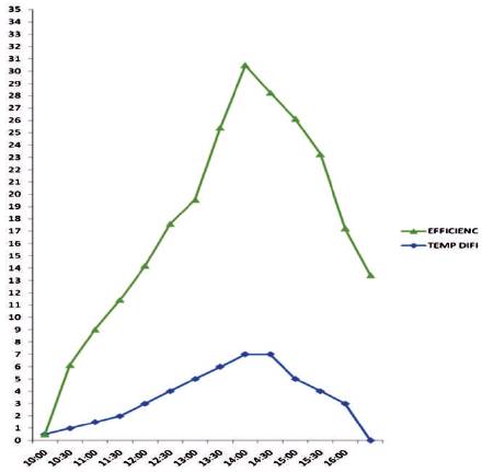
Figure 9. Temperature difference and thermal efficiency with different flow rate 0.08 kg/sec
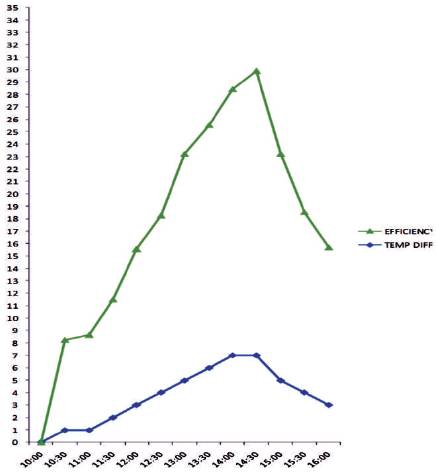
Figure 10. Temperature Difference and Thermal Efficiency with Different Flow Rate 0.09 kg/sec
As the time passes, the temperature of the water increases and efficiency of collector also increases.
In the present work, the performance of a new parabolic trough collector with hot water generation system is investigated through experiments over one full day in summer period. The maximum value of each of those parameters is observed around noon, when the incident beam radiation is at its peak. The fabrication and design of a solar parabolic trough using locally available materials is possible hence low temperature trough will be a better solar thermal device for the rural and remote area. From the result, it has been seen that the parabolic trough is a better option during winter season for reducing the water heating cost. As other forms of energy are fast depleting and polluting the atmosphere, nonconventional energy resources like solar energy are best suited to use. The solar parabolic trough is among the best way to use solar energy efficiently due to its advantages to convert abundantly available solar energy into effective and convenient form of heat energy which can be used for various purposes.