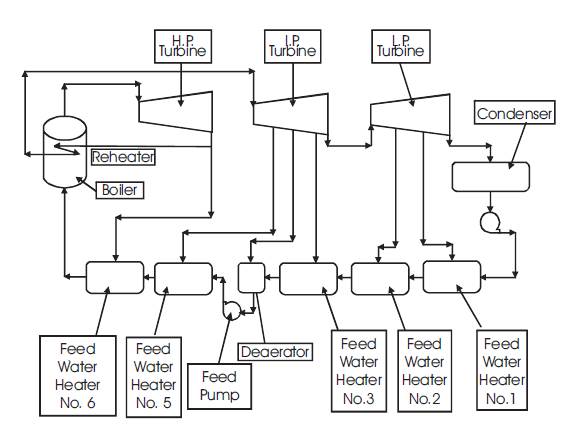
Figure 1. Schematic Diagram of a Coal Fired Thermal Power Plant
This research work is based on coal fired thermal power plant. Component wise exergy, exergy destruction rates and exergy efficiencies are evaluated for the power plant. The component/device which has higher exergy, higher exergy destruction rate or which has lower exergy efficiency is identified. This work can be analyzed by manual calculations, but this method is hectic and also has chance of human error. So a computer software is designed for component wise analysis at various operating conditions. This software is also used to analyze exergy, exergy destruction rate and exergy efficiency for other coal fired thermal power plants. This work can be concluded as, maximum exergy destruction occurs in boiler for both plants, and maximum second law efficiency is achieved in steam turbine. Therefore, when amount of fuel used in the boiler increases, the exergy destruction rate increases and second law efficiency decreases. Effects of different ambient temperatures on the performance of the plants are observed, and for condenser, if mass flow rate of circulating water increases then the exergy destruction rate decreases and second law efficiency increases.
This research work is accomplished with coal fired thermal power plants. Coal fire power plants have the following important components – high pressure steam generator, High Pressure (HP) steam turbine, Intermediate Pressure (IP) steam turbine, Low Pressure (LP) steam turbine, condenser, low pressure feed water pump, three low pressure feed water heaters (indirect contact type), deaerator (direct contact type) heater, high pressure feed water pump and two high pressure feed water heaters (indirect contact type). Working fluid (steam/water) flows through different components in a sequence as mentioned earlier. In the high pressure steam generator, constant pressure heating process is done, thus feed water is converted into high pressure and temperature steam. Then this steam enters into high pressure steam turbine where the steam is expanded. After expansion in HP turbine, steam enters into intermediate pressure turbine, and the steam is again expanded. And finally, steam enters into low pressure turbine, where the steam is finally expanded up to wet steam. At exit from LP turbine, the steam is converted from superheated steam to wet steam. Steam is fully converted into saturated water in condenser by condensing process which is also done at constant pressure. Then saturated water is pumped by LP pump into LP feed water heater. Feed water is heated in LP feed water heaters by extracted steam from LP/IP steam turbines. Then heated feed water is admitted in deaerator, and it is mixed with the extracted steam and makeup water. Then feed water is again pumped by HP pump into HP feed water heaters. In HP feed water heaters, water is heated by extracted steam from HP steam turbines, and finally, feed water enters into the steam generator. Schematic layout of coal fired thermal power plant is shown in Figure 1 (Yadav 2009, Nag 2009, Cotton 1993, BHEL 2010, Cengel 2006).
Figure 1. Schematic Diagram of a Coal Fired Thermal Power Plant
Kaushik et.al (2011) have compared energy/exergy analysis of various power plants and gave recommendations to improve the existing thermal power plants. Guoqiang et.al (2011) have worked on 300MW Thermal power plant. The sites which have largest energy losses have been identified. Ehsan et.al (2011) have studied 240MW Turkish power plant and then, they have compared the performance of that power plant with others. Vosough Amir ( 2012) has calculated energy/exergy for the boiler. Mali D. et.al (2012) have introduced an easy method for exergy analysis of thermal power plant. They have analyzed the plant on the basis of quantity and quality. Sachdeva B.K. et.al (2012) have optimized the performance of steam power plant through energy and exergy analysis, and they have identified those conditions at which the performance of the plant is good. Likewise, other researchers have done work on thermal power plant and they have analyzed on the basis of energy / exergy. They have also identified/quantified losses and suggested different ways to improve the performance of the plants(Geete A. et.al, 2013, 2014) .
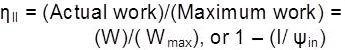
In this research work, exergy, exergy destruction rate and exergy efficiency are analyzed at different operating conditions, and a computer software is developed for these analyses (Steven H., 2000) . This computer software can be used to analyze and compare the performance of various power plants. In this paper, exergy, exergy destruction rate and exergy efficiency terms are used, where these terms are defined as – exergy; a term used in thermodynamics to designate the maximum work, a system can perform on moving from a given state to equilibrium with its surroundings. The work done by a system in a particular thermodynamic process is maximal only if the process is an equilibrium process. Exergy destruction rate; is the wasted work potential during a process as a result of irreversibility. Exergy efficiency; is also known as second law efficiency and it is the ratio of actual exergy to ideal exergy or actual available energy to ideal available energy.
Component wise exergy analyses of coal fired thermal power plant are done in this research work. These analyses are completed by manual calculations and also with the help of a designed computer software. Manual calculations are done by componet wise exergy equations and the software is developed by Visual Basic software. General expression for maximum work of an open system is (Nag 2009) ,
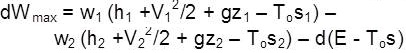
where w1 and w2 are mass flow rates of working fluids at the inlet and outlet, h1 and h2 are specific enthalpies of working fluid at the inlet and outlet, V1 and V2 are velocities of working fluid at the inlet and outlet, z1 and z2 are elevations at the inlet and outlet, s1 and s2 are entropies of working fluid at inlet and outlet, To is ambient temperature and E is total energy of the system. Now mass flow rates are same, then neglecting K.E., P.E. and system energy, the maximum work for per unit mass is,

Energy balancing equations for per unit mass for open and closed systems are respectively,

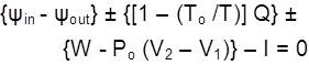
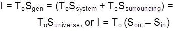
where {ψin - ψout } is rate of change of exergy, {[1 – (To/T)] Q} is the rate of change of exergy between system and the surrounding (here T is the temperature at which Q heat transfer takes place), W is the actual work transfer from the system and I is exergy destruction, and sign of the heat/work transfer depends on the direction of flow of energy.
Following equations for per unit mass flow rate are used during analysis (Cengel 2006), and all the Figures (Figures 2 to 14) for different components are drawn according to the plant layout (BHEL 2010)


Exergy destruction by Gouy-Stodola theorem,
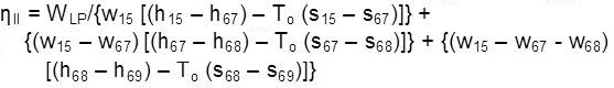
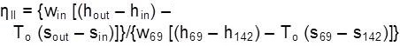
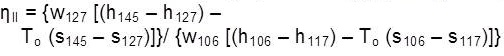
Exergy efficiency or second law efficiency,
As per Figure 2, the schematic diagram of boiler,

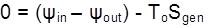

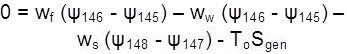

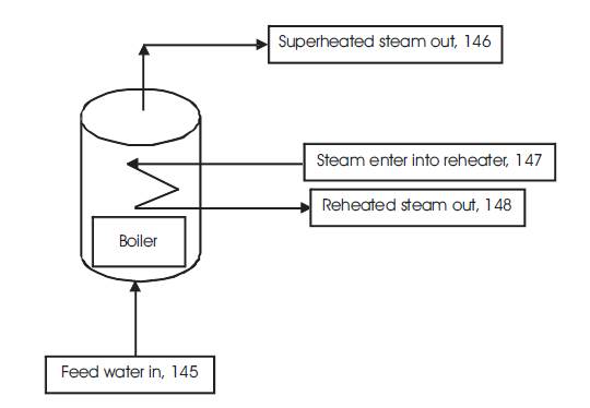
Figure 2. Schematic Diagram of Boiler


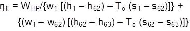
As per Figure 3, the schematic diagram of high pressure steam turbine,


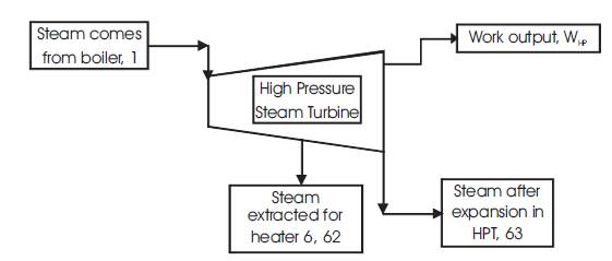
Figure 3. Schematic Diagram of High Pressure Steam Turbine
Based on Figure 4, the schematic diagram of intermediate pressure steam turbine,
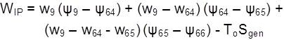

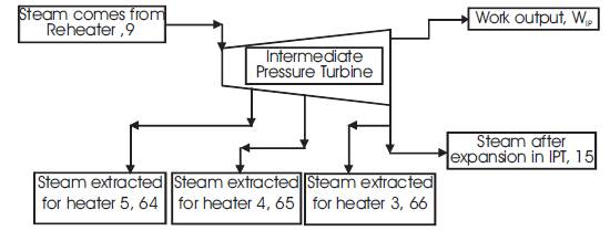
Figure 4. Schematic Diagram of Intermediate Pressure Steam Turbine

According to Figure 5, the schematic diagram of low pressure steam turbine,
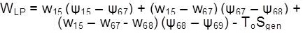

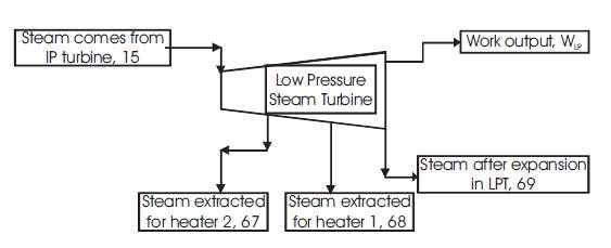
Figure 5. Schematic Diagram of Low Pressure Steam Turbine
According to Figure 6, the schematic diagram of condenser,


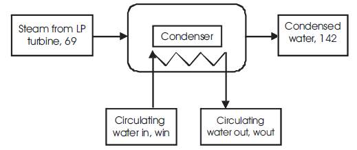
Figure 6. Schematic Diagram of Condenser
According to Figure 7, the schematic diagram of low pressure pump,
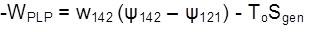

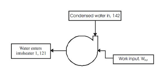
Figure 7. Schematic diagram of low pressure pump

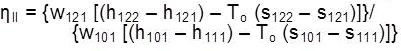
As per Figure 8, the schematic diagram of feed water heater 1,

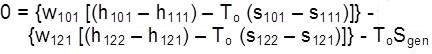
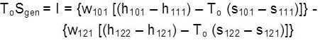
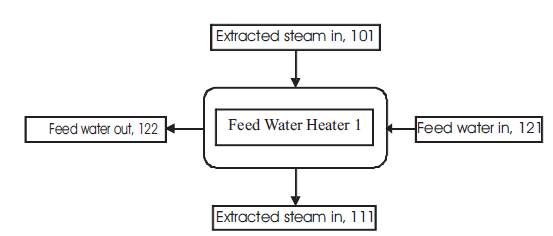
Figure 8. Schematic Diagram of Feed Water Heater 1
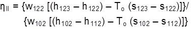
As per Figure 9, the schematic diagram of feed water of heater 2,

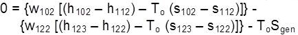
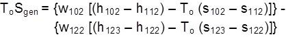
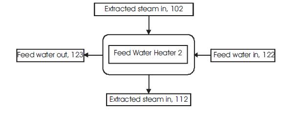
Figure 9. Schematic Diagram of Feed Water Heater 2
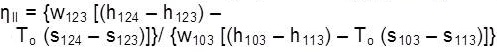
From Figure 10, the schematic diagram of feed water heater 3,

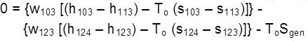

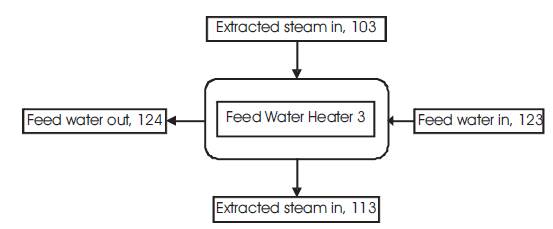
Figure 10. Schematic Diagram of Feed Water Heater 3
From Figure 11, the schematic diagram of feed water heater 4,


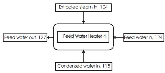
Figure 11. Schematic Diagram of Feed Water Heater 4
According to Figure 12, Schematic diagram of high pressure pump,


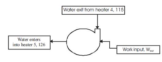
Figure 12. Schematic Diagram of High Pressure Pump

From Figure 13, the schematic diagram of feed water heater 5,


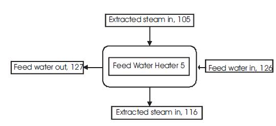
Figure 13. Schematic Diagram of Feed Water Heater 5

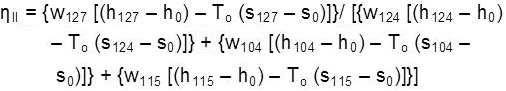
From Figure 14, the schematic diagram of feed water heater 6,


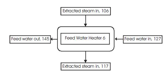
Figure 14. Schematic Diagram of Feed Water Heater 6
Important thermodynamic properties of two different coal fired thermal power plants are given below, first is for 120MW and other one is for 670MW thermal power plant. All the properties are taken from plant layouts as shown in Table 1 and Table 2 (BHEL 2010 , Geete A. 2014) . These properties are used for exergy analysis from the designed computer software and also used for component wise comparison of the plants. From the designed software, actual workouts are calculated for two different coal fired thermal power plants.
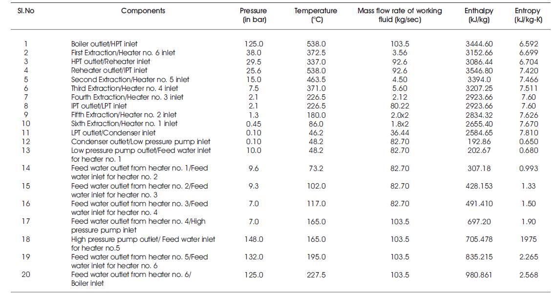
Table 1. Thermodynamic Properties of a Coal Fired Thermal Power Plant
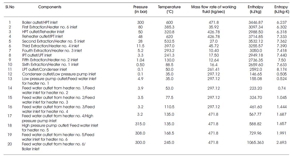
Table 2. Thermodynamic Properties of Another Coal Fired Thermal Power Plant
This is the main form of the designed software which is used for component wise analysis of the plant as shown in Figure 15. Visual Basic language is adapted to prepare this software (Steven H. 2000) . To operate this software, all the blank text like enthalpy/entropy should be filled and by clicking the command button, all the results can be found out. Flow diagram of how the software is operated is shown in Figure 16.
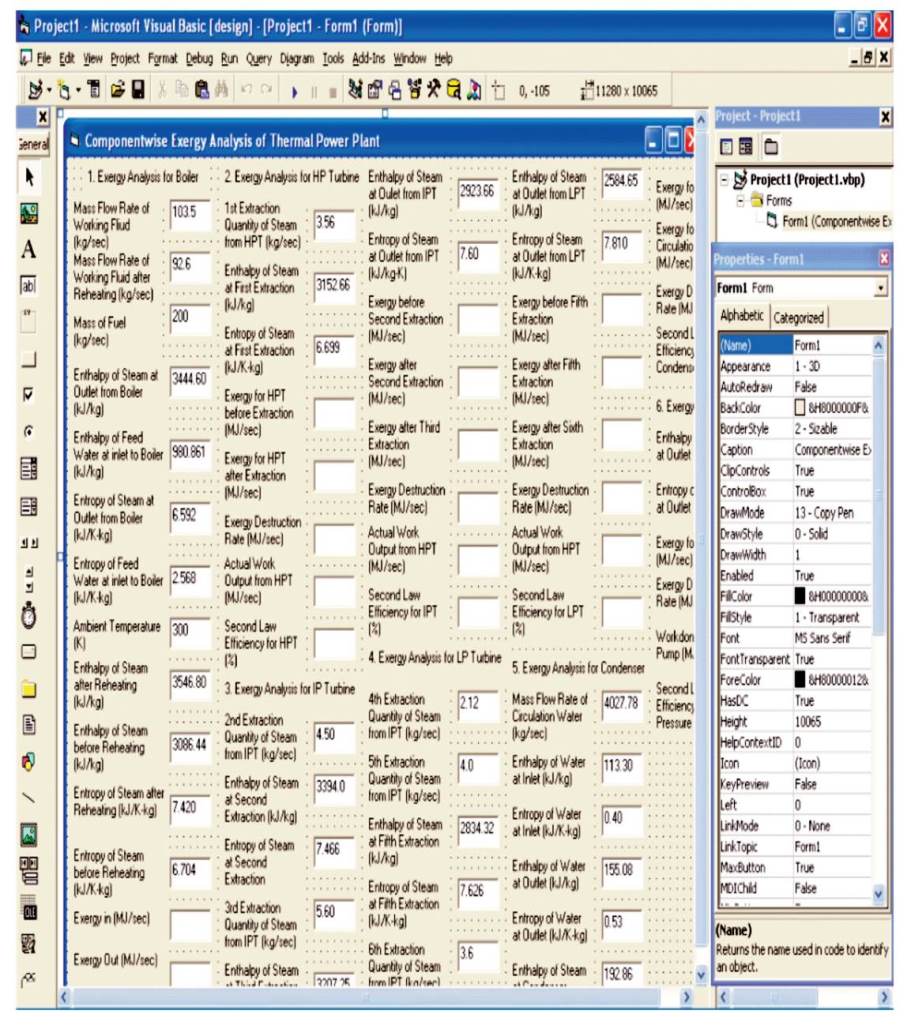
Figure 15. Main Page of the Designed Computer Software for Component Wise Exergy Analysis
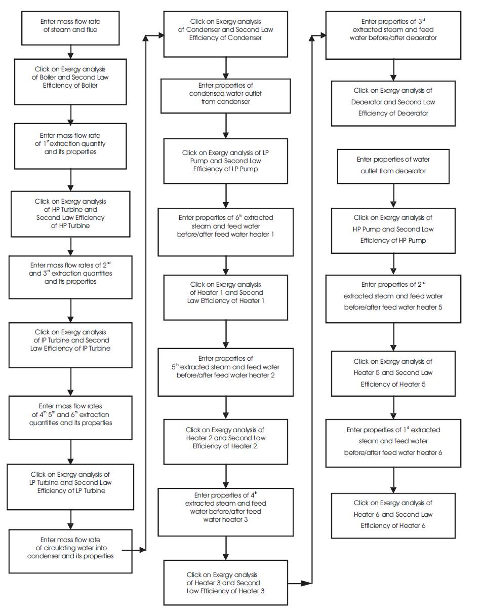
Figure 16. Flow Chart of the Designed Computer Software
From the designed software, exergy analysis for boiler, high pressure turbine, intermediate pressure turbine, low pressure turbine, condenser, low pressure feed pump, feed water heater 1, feed water heater 2, feed water heater 3, feed water heater 4, feed water heater 5, feed water heater 6 and for high pressure feed pump are done. Mass flow rates at different stages are also calculated with the help of the software as shown in Figure 17 and Figure 18.
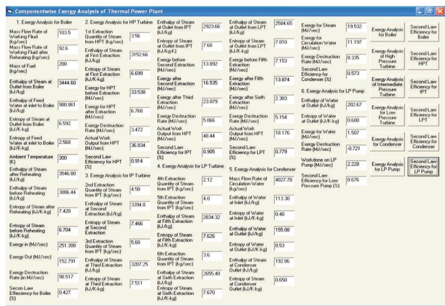
Figure 17. Component Wise Exergy Analysis of Power Plant
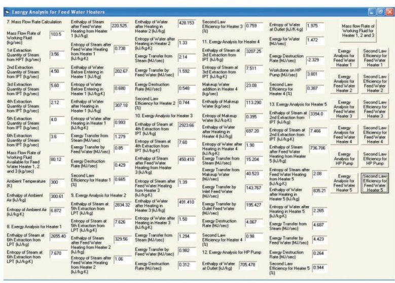
Figure 18. Component Wise Exergy Analysis of Power Plant
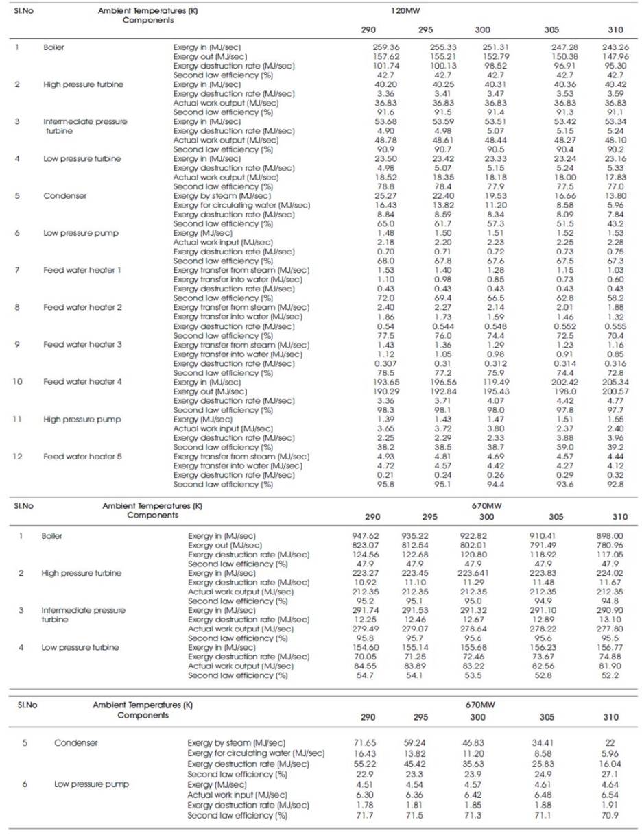
In this research analysis, exergy in, exergy out, exergy destruction rate and second law efficiency are calculated for different coal fired thermal power plants. Component wise exergy analyses for different amount of fuel and for different ambient conditions are done. Following results are found from software. All these results are shown in Tables 3-6.
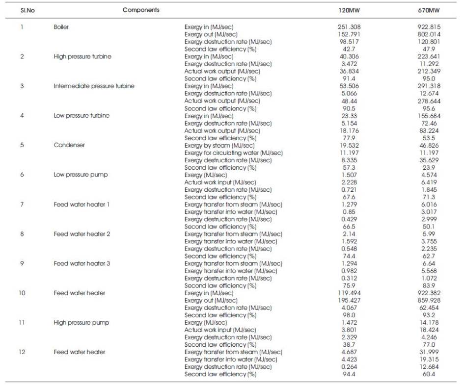
Table 3. Component wise Exergy for 120MW and 670MW Thermal Power Plant at Designed Conditions
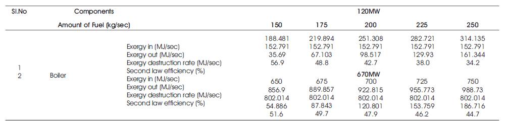
Table 4. Component wise Exergy for 120MW and 670MW Thermal Power Plant at Various Amounts of Fuel Consumption
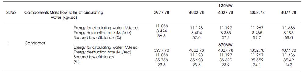
Table 6. Component wise Exergy for 120MW and 670MW Thermal Power Plant at Various Mass Flow Rates of Circulating Water in Condenser
This research work can be used to identify and quantify that component which has highest or lowest exergy (available). It is also used to find the component which has highest second law efficiency. This research work is done on various operating conditions, so it is easy to find those operating conditions at which the power plant gives better performance. From analysis on 120MW and 670MW coal fired thermal power plant, this research work can be concluded as,
h = Specific enthalpy of working fluid at different stages (kJ/kg).
I = Exergy destruction rate at different conditions (kW).
s=Specific entropy of working fluid at different condition (kJ/kg-K).
T = Temperature of working fluid at different condition (K).
w = Mass flow rate of working fluid at different stages (kg/sec).
W, WPLP and WPHP = Actual work transfer, work transfer for low pressure pump and high pressure pump respectively (kJ/sec).
ψin andψout = Exergy at inlet and outlet respectively (kW).
ηII= Exergy efficiency or second law efficiency (%).