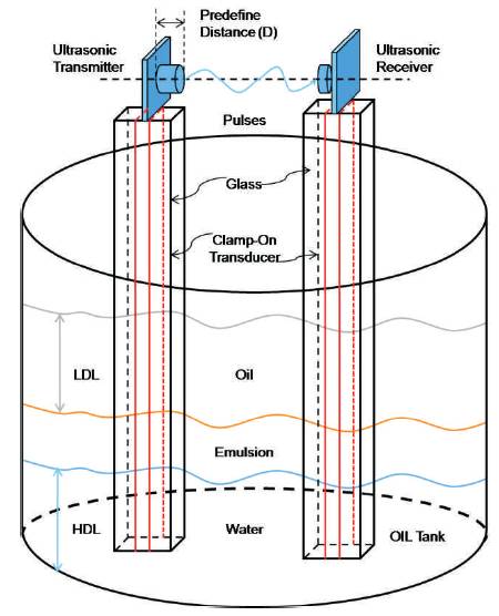
Figure 1. Multi-layer Ultrasonic Level measuring technique tank layout
This Paper explains the design, construction and installation of Multi-Layer Ultrasonic Level Measuring device stand, which makes the device contactless from liquids in an oil tank. The appropriate design of the multi-layer ultrasonic level measuring device (MLULM) stand helps for accurate measurement of level or interface level of the liquids to determine and examine the propagation of the ultrasonic wave pulse in oil, oil-water mixture (Emulsion or rag layer) and water liquids. A common measurement in these industries for detecting the interface level between two liquids or mixed liquids in the Oil refinery tank or vessel, such as oil, water and mixed liquids (Emulsion) is a must [ 5-9]. The difference in specific gravity or density of the two liquids in the refinery tanks shows that the lower density liquid will float on top of the higher density liquid in the oil refinery tank. But an emulsion or water-oil mixed rag layer will exist between the oil and water liquids [ 16, 4]. This interface situation creates multiple interfaces between more than two products or the interface between a lower density liquid and a higher density liquid in the oil refinery tank. An oil refinery does not want any water to enter the distillation process. Accuracy is very important here because any crude oil in the water means product losses, and presence of water in the oil requires extra inlet separation processing for refinery Industry [ 11-14]. The Separation of the Liquids in the refinery tank is done easily due to a difference in the density or specific gravity of the Liquids. This difference is enough to cause the water and oil to be separate. It may be too small of a difference on which to base an interface measurement. Some variables are required to control the process such as the overall level value needed as well as the interface and the thickness of the upper layer to prevent cross contamination of the separate liquids.
In oil & gas, Petrochemical, and chemical industries, many parts of the world are still facing the problem of producing water and gas together with oil from their oil wells and fields [ 10]. Separating these three components (Water, Oil, and Gas) from each other is a must. In many applications of petroleum, petrochemical and oil industry, requires the measurement of more than one liquid level interface, often in a challenging environment. This Multi-layer Ultrasonic level measuring technique is expanded to determine the different layer of liquids or mixed liquids, oil, emulsion and water levels in the oil Tanks. The new Multi-Layer Ultrasonic Level Measuring (MLULM) technique, having certain advantage over the current methods include contactless distance measurement, higher accuracy, lower cost, user friendly, simpler setup, and usage of non-nuclear rays [ 15, 19]. Additionally, the use of ultrasonic waves for the measurement has the advantage over light-based methods of being insensitive to dusty and smoky environment and almost independent of the object material and surface.
The actual intent of Multi-Layer Ultrasonic Level Measuring technique is to measure the amount of ultrasound waves transmitted and received and also its speed which is depends upon the density of the liquid. The acoustic impedance of the water and oil are different. Therefore, different response (in terms of the magnitude of theINTRODUCTION In oil & gas, Petrochemical, and chemical industries, many parts of the world are still facing the problem of producing water and gas together with oil from their oil wells and fields [ 10]. Separating these three components (Water, Oil, and Gas) from each other is a must. In many applications of petroleum, petrochemical and oil industry, requires the measurement of more than one liquid level interface, often in a challenging environment. This Multi-layer Ultrasonic level measuring technique is expanded to determine the different layer of liquids or mixed liquids, oil, emulsion and water levels in the oil Tanks. The new Multi-Layer Ultrasonic Level Measuring (MLULM) technique, having certain advantage over the current methods include contactless distance measurement, higher accuracy, lower cost, user friendly, simpler setup, and usage of non-nuclear rays [ 15, 19]. Additionally, the use of ultrasonic waves for the measurement has the advantage over light-based methods of being insensitive to dusty and smoky environment and almost independent of the object material and surface. Objective and Findings The actual intent of Multi-Layer Ultrasonic Level Measuring technique is to measure the amount of ultrasound waves transmitted and received and also its speed which is depends upon the density of the liquid. The acoustic impedance of the water and oil are different. Therefore, different response (in terms of the magnitude of the received ultrasound wave pulse) of both liquids should be expected. Hence, by measuring the signal response at different vertical positions in the tank the two levels of the interface can be measured. Such separation is usually done in stages [ 17-18]. In one of these separation stages oil and water mixture is allowed to settle in large tanks for a short period of time. This process will cause the oil and water mixture (Emulsion) to separate. However, the separation will consist of three components, oil (lower density liquid) at the top, oil/water mixture in the middle, and water (higher density liquid) at the bottom. Water will then be pumped out from the tank. However, in order to not pump out oil with water, the level of the mixed liquid (water-oil or Emulsion) need to be monitored continuously, especially during the pumping process. In [ 7, 20] an extensive literature review on currently available level measurement methods, measuring devices and sensors have been investigated. The author claimed that most of the devices have been designed to detect only the level of the top of the liquid in the tank. These measurement sensors include RF capacitance, conductance, nuclear, radar, differential pressure, optical switches, and ultrasonic. A microwave based sensor is among the fewer devices which have been recently designed for extraction of the levels of the emulsion layers in the tank [ 1- 3]. However the system is expensive. Additionally, the high energy of the microwaves make the solution inappropriate for combustible liquids. The actual results are very encouraging and demonstrate that the device can easily measure, with a very good accuracy, the interface in a single vessel. Furthermore, since its electronics is placed outside the tank, the device can work in hazardous, clean, or sterile environments and cope with surface foam or bottom sludge. Hence the approach can be extended to allow the measurement of other fluid types as well.
In this paper, a new ultrasonic-based hardware device Stand for MLULM is presented. The hardware design of both the ultrasound devices and the device holder tank as well as the placement of the sensors in the tank with the stand are described in Figure 1. The property of the Ultrasonic transducer such as frequency and amplitude will also be defined. The acoustic impedance of water (1.4) and oil (1.07) respectively are different. Therefore, different response (in terms of the magnitude of the received ultrasound pulse) of both liquids should be expected. Hence, by measuring the signal response at different vertical positions in the tank the two levels of the interface can be measured. Figure 1 shows the layout of the tank. An ultrasonic transmitter and receiver are mounted on two separate stands, at the same horizontal level of the tank. The signals from the receivers shall provide a complete profile for the contents present in the oil refinery tank. The advantage of this layout design is that the results are independent from the geometrical and chemical properties of the walls of the tank. It's composed of an ultrasonic transmitter receiver pair placed orthogonal to one another inside the two vertical stands and transmitting at a programmable frequency. The frequency range for ultrasonic methods is in the range of 15 to 200 kHz. The lower frequency instruments are used for more difficult applications; such as longer distances and solid level measurements and those with higher frequency are used for shorter liquid level measurements. Generally, the measurement of interface of two liquids or mixed liquids are required at the time of pump-out of the water or higher density liquids (generally water) from the oil refinery tank. This process required overall control that the overall level as well as the interface and the thickness of the Low Density Liquid level to avoid cross contamination of the separate liquids.
Figure 1. Multi-layer Ultrasonic Level measuring technique tank layout
Where
LDL = Low Density Liquid.
HDL = High Density Liquid.
And in between these two Liquids an emulsion or rag layer or mixed liquids is present.
This paper describes the Multi-Layer Ultrasonic Level Measuring technique for measurement of the level or interface point of two liquid with ‘contact less method’ by an ultrasonic sensor. The advantages of the ultrasonic level measuring are low price of transducers, simplification of processing the information and the fact that changes in pressure, temperature or type of materials in container do not affect measuring. The measuring transducer is designed for implementation in the established standard automation systems.
In the ultrasonic Transmitter,a programmable timer should be used to generate the signals e1(t) = A cos (2πf0t) as shown in Figure 2. Then this generated signal is mixed with carrier signal in multiplier and Controller. The dedicated Square Wave Generator oscillators generate the analogue signal e2(t) = A cos (2πf1t+θ) respectively as shown in Figure 3. This Carrier signal is mixed with reference signal in multiplier and controller [ 6-7]. These two oscillators which generate the analogue signal e1 (t) = A cos (2πf0t) and e2 (t) = A cos (2πf1t+θ) respectively. These two signals are then fed to a multiplier and controller to generate a mixed signal, e3 (t) = A2 [cos (2πf1t+θ)*cos (2πf0t)].The resultant signal of two different signals should be fed to Bridge amplifier before emitting through the Ultrasonic Transmitter. The Train of ultrasonic pulses which drives the Ultrasonic Transmitter (TX) converts the analogue electric signal, e3 (t) as shown in Figure 4 into acoustic waves, which should pass through the transmitter stand and the liquid medium of the oil refinery tank before they reach the ultrasound receiver.
Where
SWG = Square Wave Generator.
PC = Personal Computer.
At = Attenuation of Transmitted ultrasonic wave.
F-V = Frequency to Voltage Converter.
Instr-Amp = Instrument Amplifier.
Ar = Attenuation of Received ultrasonic pulse.
The ultrasonic received signal was amplitude-modulated and the two parameters Δφ and Ar/At are very sensitive to the position of the ultrasound sensors in the tank. Phase difference of the transmitted and received ultrasonic wave is given as,

And damping ratio is given as,

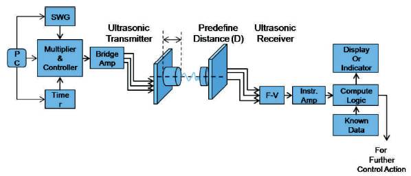
Figure 2. Block Diagram of Ultrasonic Transmitter and Receiver with Ultrasonic Sensor
The Ultrasonic receiver receives the ultrasonic sound wave signal and this frequency signal transfer to the frequency to voltage converter. Then the collected frequency signal should be converted to an appropriate amount of voltage with high gain op-amp/comparator designed to operate a relay, lamp, or other load when the input frequency reaches or exceeds a selected rate by using frequency to voltage converter. This appropriate voltage signal should be fed to the Instrument amplifier in which the amplification of the signal is done, providing good dc and ac accuracy with fewer components. This circuit block utilizes difference amplifier and two Non-Inverting amplifiers, which have low drift, low noise, high speed, and low offset,. For high impedance sources, the Non- Inverting Amplifier is an ideal choice for the input stage amplifiers due to the extremely low input bias current. The nd amplified signal is then fed to a 2 order antialiasing filter to create a pure amplified signal of frequency. This instrument amplifier system transfers the amplified voltage signal, then the collected amplified signal to a Computational logic blocks in which this analog amplified voltage signal is converted into digital signal by 12-bit Analog to Digital Converter (ADC) with a high speed. And the other computational Digital Signal Processing algorithm is performed. The analysis of the ultrasonic received signal in the frequency domain has the advantage to provide accurate results, regardless of the amount of noise surrounding the device. Another output of the amplifier, which detects a portion of the received signal having significant amplitude is fed to a comparator. This allows an immediate of the delay between the transmitted and received pulses in the time domain.
The ultrasound pulse reaches the receiver after a delay as shown in Figure 3.

Where Dt and Dp are the depths of the tubes and the distance separating the two vertical stands respectively [6, 7], whereas vt and vp are the sound velocity in the vertical stand and the liquid respectively. The oil and water have a significant difference of velocity of the ultrasound waves. Hence, to have a significant difference of delay, the distance separating the two transmitter and receiver stands should be high (e.g. at least more than 1 cm). However, this may be an additional damping of the ultrasonic waves. Therefore, the design of the tank was performed in such a way that the distance of the two stands can be easily modified.
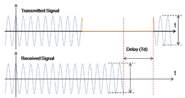
Figure 3. Graph show the Transmitted and Received Signal with Delay (Td)
There are certain influencing factors which can affect the attenuation of the received ultrasonic sound waves by reflecting the transmitted signal. At a boundary between two objects (e.g., liquid-MLULM stand) with different ultrasonic impedances, there is a reflection. The reflection coefficient is directly related to the impedance difference between the two media [ 3].This led to use the glass as shown in Figure 4 and 5. Since its property is simultaneously close to the water and oil,the speed of ultrasound waves in water is faster than in the oil. Also, the repeatability for both the delay and the damping is good. The material which is selected for the designing of MLULM stand is because of its property or material density which is similar to property or density of liquid or water.
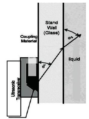
Figure 4. Diagram showing ultrasonic Waves travelled with the Stand Glass Material
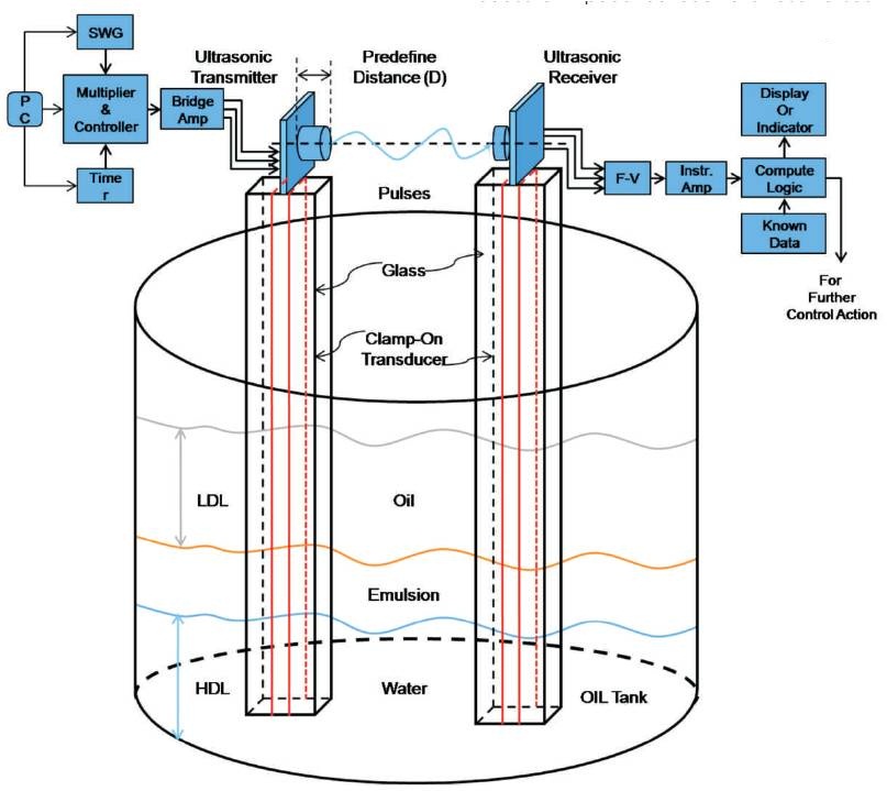
Figure 5. Complete Diagram of MLULM Device
The multi-layer ultrasonic level measuring device stand helps for accurate measurement of level or interface level of the liquids to determine and examine the propagation of the ultrasonic wave pulse in oil, oil-water mixture (Emulsion or rag layer) and water liquids. The material of the stand is selected in such a way that the acoustic impedance due to ultrasonic sound doesn't influence the attenuation. The advantages of Multi-layer Ultrasonic Level measuring technique over the present available techniques can be summarized as follows:
The Ultrasonic sound waves received by the ultrasonic receiver should be converted into the appropriate amount of Voltage signal with high gain opamp/ comparator designed to operate a relay, lamp, or other load when the input frequency reaches or exceeds a selected rate by using frequency to voltage converter.
This Frequency to Voltage Converter (F-V) transfer the voltage signal to Instrument amplifier, in which the amplification of the Signal is done, which provides good dc and ac accuracy with fewer components. This instrument Amplifier system transfers the amplified voltage signal, then the collected amplified signal to a Computational logic blocks in after which is analog amplified voltage signal is converted into digital signal. And the other computational Digital Signal Processing algorithm is performed. A suitable calibration procedure was implemented. Therefore, the method represents an important system in comparison with other methods such as determining the composition fraction of oil and water in multiphase systems. Moreover, this Multi-Layer Ultrasonic Level Measuring technique can be used for level measurement of toxic, hazardous, Non-corrosive or corrosive liquids. This idea of developing Multi-Layer Ultrasonic Level Measuring technique is the first step towards the measurement of liquid-liquid interface and liquid-solid interface system. The time domain with magnitude and amplitude of signal analysis of the received ultrasonic sound waves provided ver y satisfactory results.