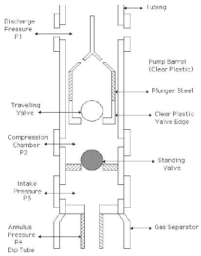
Figure 1. Plunger pump diagram
In this paper a numerical model for calculating plunger pump leakage is introduced. This model involves calculating the velocity profile for an annulus with the inner wall moving parallel to the outer wall. The calculated average velocity for the annular fluid is used to predict the fluid slippage. The new method for the slippage agrees with published formula at the same operating conditions. The numerical model is used to predict the fluid slippage at different operating conditions.
A representative plunger pump is shown in Figure 1. It can be used for all types of sewage, sludge, scum, slurries, and clarifier and thickener underflow. It can be applied for transfer and for metering service. Such pumps are available in single and multi cylinder models. The plunger contains the crosshead, driven by a camshaft arrangement. The capacity of the pump can be adjusted by changing the stroke, or the rotating speed of the pump, or both. The stroke of the pump is changed by the eccentric pin setting.
A plunger pump is equipped with single or dual ball lift check valves. The dual design contains two ball check valves in series for each plunger on both the suction and the discharge side. Two valves rarely hang up on foreign matter at the same time, so if one valve is unseated the other continues to operate properly until the foreign matter is flushed through without affecting the pump operation. "Quick-opening" covers provide for easy access to the ball checks and seats for servicing or replacement. Plunger pumps should be designed and operated at the maximum discharge stroke setting for the best operation [1-5].
Proper pump slippage is a balance between proper lubrication to extend the life of the pump and enhance pump volumetric efficiency. A plunger can stick if the clearance between the pump barrel and pump plunger is too small. The clearance must be large enough to allow an appropriate amount of slippage to sufficiently lubricate the plunger. In order to predict pump performance and design for proper lubrication, pump slippage needs to be accurately modeled either mathematically or experimentally [6, 7].
Very recently Ma et al.[8] presented a single and multi-cylinder piston pump dynamics, in where they considered some typical equations to evaluate the leakage across the different piston/barrel gaps. They studied very carefully the leakage across the triangular timing grooves; they also considered the fluid inertia of the timing grooves, the simulated pressure ripple was compared with the experimental one clarifying the effect of the timing grooves regarding the piston dynamics, they also optimized the timing groove length for a particular application.
Bergada et al.[9] presented a research focused on understanding the flow losses and the resulting flow/pressure dynamics in a piston pump. Initially, equations to evaluate leakages in all piston pump gaps were presented and tested against numerical models, later the equations were linked to determine the general pressure/flow pump dynamic characteristics. The model provided the temporal pressure in each piston/cylinder chamber and the temporal leakage in all pump clearances. A test rig able to measure the dynamic pressure inside a piston chamber was build and employed to evaluate pressure ripple dynamics as a function of turning speed, outlet pressure and swash plate angle. The advantage of using the analytical approach is that explicit equations allow a more direct understanding of the effect of dimension changes and operating conditions on pump dynamics.
Many empirical formulas have been developed to predict the pump slippage over the years[10-12]. However, these formulas over predict the pump slippage and therefore more accurate formula is needed. In this paper a numerical model for calculating slippage is introduced. This model involves calculating the velocity profile for an annulus with the inner wall moving parallel to the outer wall. The calculated average velocity for the annular fluid is used to predict the fluid slippage.
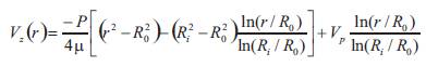
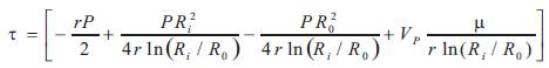
In a plunger pump shown in Figure 1 with a stationary barrel and a moving plunger, the velocity profile between the barrel and plunger can be calculated as follows [6]:
Figure 1. Plunger pump diagram
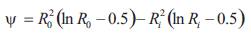
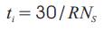
The average velocity of the fluid can be calculated to determine the fluid slippage as follows:
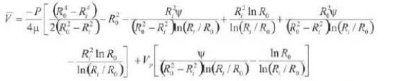
where,
The average fluid velocity for concentric plunger can be calculated by multiplying Eq. (2) by the annular area and incremental travel time.
Calculate a slippage for each stroke length increment and sum up all of the incremental slippages to calculate a total slippage for one stroke.
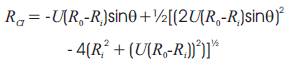
For eccentric plunger the fluid slippage can be calculated by using a different plunger radius in the average velocity equation (Eq. 2) as follows:
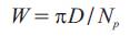
the average velocity is multiplied by the width of the element, average clearance, and incremental travel time. The width of the element can be calculated as follows:
The drag force on a concentric plunger [13],
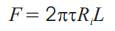
Where,
Once the slippage is calculated for each element of the cross-section, the summation of all elements represents the slippage at that stroke increment cross-section. The procedure is repeated for each stroke increment cross-section and summed to determine the pump slippage per stroke.
The above governing equations were solved to calculate the plunger pump slippage using a FORTRAN numerical model assuming constant rotational speed and sinusoidal plunger motion.
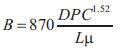
The laboratory test data obtained at the Southwestern Short Course (Patterson et al.[10-12] ) on the subject of slippage is used to drive the ARCO- Harbison Fisher equation, as:
The present model agrees with the ARCO-Harbison Fisher equation (Patterson et al. [10-12]) at the same operating conditions as shown in Figure 2. The slippage values for the present model do not match the ARCO-Harbison Fisher at larger clearances (up 0.07 mm) due to entrance effects when the fluid first enters the clearance space, causing an initial pressure drop.
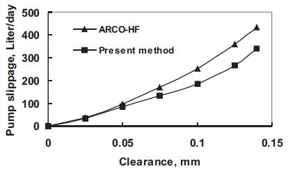
Figure 2. Comparison between the present model and ARCO-HF formula
Using conditions in Table 1, a numerical study of the effect of parameters varying on the pump slippage was carried out for a concentric and eccentric plunger. A concentric plunger is one that is centered in the pump barrel while an eccentric plunger is one that is not centered in the barrel.
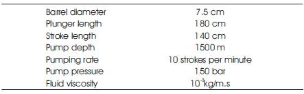
Table 1. Conditions used in the study
Figures 3 and 4 represent the effect of pumping pressure on slippage at different clearances for both concentric and eccentric conditions. Eccentricity has much larger effect on slippage than the concentricity as shown in Figures 3 & 4. Eccentricity can affect the slippage by as much as a factor of 2.5 or more.
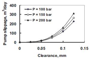
Figure 3. Slippage at different pumping pressure for concentric condition
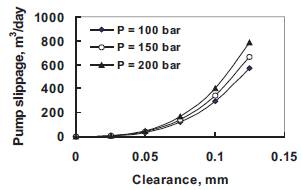
Figure 4. Slippage at different pumping pressure for eccentric condition
Pumping rate effect on pump slippage verses clearance for both concentric and eccentric conditions is shown in Figures 5 and 6. Increasing pumping rate increases the plunger pump slippage. Eccentricity has much larger effect on slippage than the concentricity. Eccentricity has a much larger effect on slippage than the pumping rate as shown in figures.
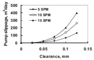
Figure 5. Slippage at different pumping rates for concentric condition
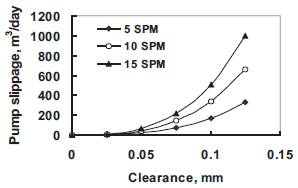
Figure 6. Slippage at different pumping rates for eccentric condition
The fluid type has a great effect on the pump slippage as shown in Figures 7 and 8. The plunger pump slippage increases with decreasing fluid viscosity especially at relatively high clearances. However, increasing pump depth has a relatively very little increase in pump slippage as shown in Figure 9.
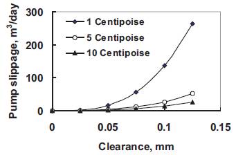
Figure 7. Slippage at different fluid viscosity for concentric condition
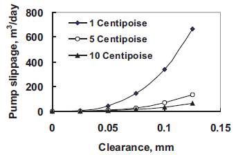
Figure 8. Slippage at different fluid viscosity for eccentric condition
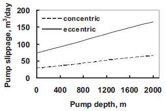
Figure 9. Slippage vs. pump depths (clearance = 0.075 mm)
A numerical model for calculating slippage is introduced. This model involves calculating the velocity profile for an annulus with the inner wall moving parallel to the outer wall. The calculated average velocity for the annular fluid is used to predict the fluid slippage. The new method for the slippage agrees with published formula at the same operating conditions. A numerical study of the effect of parameters varying on the pump slippage was carried out for a concentric and eccentric plunger. The results showed that the eccentricity has much larger effect on slippage than the concentricity. The present numerical model can be used for accurate prediction of plunger pump slippage for a wide range of variables.
| C | Plunger-barrel clearance, m. |
| D | Barrel diameter, m. |
| L | Plunger length, m. |
| Np | Number of increments of plunger cross section. |
| Ns | Number of increments of stroke. |
| P | Pressure over plunger, Pa |
| R | Pumping rate, stroke/min. |
| r | Radius, m. |
| Vp | Plunger velocity, m/s. |
| Vz | Fluid velocity as a function of radius, m/s. |
| W | Width of plunger element, m. |
| μ | Dynamic fluid viscosity, centipoises. |