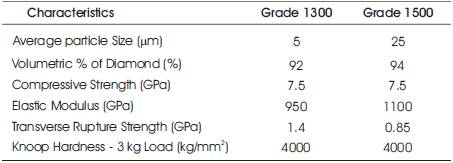
Table 1. Characteristics of the various grades of PCD inserts used
The applications of composite materials based on Carbon Fiber Reinforced Plastic (CFRP) have been increasing considerably in aerospace industries, because of their good physical and mechanical characteristics. It is necessary to develop new manufacturing process and production techniques to ensure good surface quality of the components. As a result of this manufacturing scenario, it is necessary to study the machining process. This study reports practical experiments in turning, to study the performance of Poly Crystalline Diamond (PCD) inserts of two different grades. The results show that diamond tools are suitable for use in finish turning. The tests were carried out with PCD inserts at various cutting speeds on a medium duty lathe of spindle power 2KW. In the optimization method, turning was done by two different grades (PCD 1300, PCD 1500) for 30 seconds duration for each trial at different cutting conditions by using design of experiments. Parameters such as power consumed by main spindle, surface roughness were measured. Graphs were drawn to analyze the performance of two different grades on various parameters. Finally, it is concluded that the PCD 1500 grade is superior in all aspects.
LeCarbon fibre reinforced plastics play major role in the aerospace and military industries because of their physical and mechanical properties [1]. Machiningof composite materials differs significantly from machining of conventional metals and alloys because of inhomogeneous and anisotropic material behaviourdependance on fiber and matrix properties and their content-the tool encounters alternatively matrix and reinforcement materials with entirely different response to machining. Thus, machining of composite materials imposes special demands on the geometry and wear resistance of cutting tools [3]. The peculiar behavior of composite materials during machining has been widely observed experimentally. A proper choice of cutting conditions is difficult due to the coexistence of hard abrasive fibers and a soft matrix. Based on the experimental observations, little plastic deformation of composite materials occurs during cutting, and the fracture resistance. Turning is the most frequently applied in the aircraft industry for generating shafts for structural assemblies [7]. Poor surface finish leads an estimated 60% of part rejection [6]. Persson et al. show that hole machining defects have significantly reduced the strength and fatigue life of carbon/epoxy laminates [11]. Capello and Tagliaferri investigated the effect of drilling conditions on the residual mechanical behavior of GFRP laminates subjected to a bearing load [2,9]. Results indicate that the main cause of mechanical failure is the micro-damage generated at the inner part of the hole surface, while elimination plays a minor role. The mechanics of drilling composite materials has been examined along with the quality of the hole and the effect of tool design parameters. The fibrils or fuzz caused by conventional tools, which cut the holes in the center and force chips against walls, can be significantly reduced. The drill geometry is considered to be the most important factor that affects drill performance [4,5,8,9,10, 12,13,14]. Most of the studies was concentrated on drilling. There were only limited numbers of literature available in turning CFRP. In this direction, an attempt has been made to investigate the machining behavior of CFRP using two different grades of PCD insert, via 1300 and 1500 grade.
Machining tests were conducted with different cutting conditions on CFRP composites of hollow cylindrical rods of outside diameter 68 mm and inside diameter 50 mm. Samples were obtained from Hindustan Aeronautical Limited (HAL, Bangalore) with 175 mm length. The tool holder used was PCLNR 25 25 M 12. The PCD insert was of geometry CNMA 120408 which is the commonly used inserts geometry for general turning application. The tool materials were 1300 and 1500 grades. Table 1 shows the characteristics of various PCD grades Medium duty lathe was used for the turning tests. The machining of the fabricated composite was performed at three different cutting speeds of 100, 150 and 200 m/min in the medium duty lathe machine. The cutting speeds were so chosen to reach the maximum cutting speed possible, for the given workpiece size. The feed rates were 0.100, 0.200 and 0.3 mm/rev. The depths of cuts used for machining were 0.5, 0.75 and 1.0 mm. All the tests were carried out under dry machining conditions. The machining was interrupted at various time intervals, power consumed by main spindle and the surface roughness of the workpiece material were measured. One of the important characteristics indicating the machinability is the power consumed in machining. The power consumed by the main spindle is measured by digital watt meter 96X96- DW 34 (serial No. 070521485) make (Nippen Electrical inst.Co. India) for all cutting conditions. The surface roughness of the machined component was measured using a Mitutoyo Surf test 301 surface roughness tester. The Ra value of the surface roughness corresponding to each machining condition was measured. The worn insert tip was observed under the Mitutoyo TM 500 Toolmaker's microscope and the flank wear land was measured. Worn tool images and machined composite bar were scanned by Scanning Electron Microscope (SEM).
Table 1. Characteristics of the various grades of PCD inserts used
Figures 1, 2 and 3 show the plot between cutting speed and Surface roughness (Ra). Average Surface roughness Ra is normally considered in industry to measure the surface roughness of the machined component. Hence, it is in this study. It is clearly observed that, cutting speed increases surface roughness decreases for all the feed rates and depths of cut. However, at depth of cut 0.5 mm with feed rate of 0.20 mm/rev show less surface roughness at high speed compared to other two feed rates. It is clearly evident that, 1500 grade insert is superior in all aspects compared to 1300 grade. This is the fact, that in 1500 grade average particle size of diamond and volumetric percentage of diamond is greater than 1300 grade. From Figure 2, it is observed that at 0.10 mm/rev feed rate of machining the composite using PCD 1500 grade shows the lowest surface roughness compared to other two feed rates. In all the depth of cut and feed rate 0.1 mm shows good result. It is clearly observed that influence of depth of cut on surface finish is not a big issue. In order to know the trend in detail, it is necessary to plot a curve between surface roughness and feed rate.

Figure 1. Cutting Speed versus Surface roughness (depth of cut 0.50 mm)

Figure2. Cutting Speed versus Surface roughness (depth of cut 0.75 mm)

Figure3. Cutting Speed versus Surface roughness (depth of cut 1.0 mm)
Figure 4 shows the graph for all feed rates and for depths of cut of 0.50 mm against the surface roughness. In order to investigate the high influence parameter on surface roughness, this plot is introduced. It is clearly evident that, for 0.50 mm depth of cut PCD inserts of 1300 grade and 1500 grade are showing increase in the surface roughness when feed increases. This is a general trend if feed increases, surface roughness increases. However 1500 grade insert showing good performance at lower cutting speed in the range of 150 m/min.

Figure 4. Feed rate versus Surface roughness (Depth of cut 0.5mm)
The similar trend exists in other feed rates also. It is evident that feed rate has higher influence on the surface finish.
From Figures 5, 6 and 7, it is observed that power consumption increases as cutting speed increases. The similar trend exists for other feed rates and depth of cut. However PCD shows better progress in the power consumption. This is believed that sharp cutting edges need less power consumption [6,2].

Figure 5. Cutting Speed versus Power Consumed (depth of cut 0.5 mm)

Figure 6. Cutting Speed versus Power Consumed (depth of cut 0.75 mm)

Figure 7. Cutting Speed versus Power Consumed (depth of cut 1.0 mm)
Figure 8 shows the Scanning Electron Micrograph (SEM) pictures of machined component surface.

Figure 8. SEM images of machined component
It was observed that fibers are pulled out from the surface. Cavity and air pockets are presented on the surface. Parallel tool marks are also visible on the surface. It shows the evidence of the tool wear is by abrasion action of the work piece.
Figure 9a shows the nose region of PCD insert of 1300 and Figure 9b shows the 1500 grade after machining the CFRP composite. Built-up edge (BUE) is high at the top rake face. It was observed that tool wear is more when machining the composite with higher cutting speeds. Tool wear is minimal at lower cutting speeds. One factor is observed that carbon particles in the composite material absorb diamond very fast. Hence tool flank wear reached the recommended value of 0.4mm with in 10 minute of time duration. It is recommended to machine the CFRP with low feed rate and low cutting speed to get good surface finish.

Figure 9a. SEM images of nose region of PCD insert (1300 grade)

Figure 9b. SEM images of nose region of PCD insert (1500 grade)
From the above investigation on machining CFRP, following conclusions are arrived.