[1]

Diesel engines are the best prime movers with substantial inherent energy transfer to the coolant. To minimize this heat transfer to the coolant, Low Heat Rejection (LHR) concept was developed. At the same time, drawbacks were also encountered because of the very high combustion chamber temperatures in LHR engines. Heavy exhaust blow-down energy and high Oxides of Nitrogen (NOx) emissions were two among them, which has lead to decrease in thermal efficiency and inability to achieve legislative emission levels. To realize the advantages of LHR diesel engine, the cycle calculations were formulated and developed under numerical simulation. The parametric studies were carried out with closer duration of each crank angle degree. In the engine cycle calculations the Internal Exhaust Gas Recirculation (iEGR) and extended expansion processes were coupled to minimize the drawbacks of LHR engine. The iEGR is accomplished with the secondary exhaust valve opening during suction stroke and the extended expansion by incorporating the Miller cycle by delaying the IVC timing. The heat release is calculated using preparation rate and reaction rate, considering two-zone combustion. The total heat transfer is calculated using Annand's combined heat transfer model. During combustion, chemical equilibrium of oxygen and nitrogen were determined to calculate the nitric oxide formation rate, assuming ZELDOVICH mechanism. The results of the numerical simulation were validated by conducting experiments in a Conventional and as well as LHR turbocharged four cylinder DI diesel engine. Modification of gas exchange has resulted in decrease in nitric oxide emissions along with a considerable improvement in thermal efficiency under LHR condition.
The diesel engine rejects about two thirds of the heat energy of the fuel, one-third to the coolant and one-third to the exhaust. By decreasing the heat transfer between the working fluid and the cylinder walls, the energy that would otherwise have been rejected to the coolant is exchanged for increased shaft work. Low Heat Rejection engines are capable to do this by reducing the heat lost to the coolant. The diesel engine with its combustion chamber walls insulated by ceramics is referred to as Low Heat Rejection (LHR) engine.
Most of the researchers have concluded that, insulation reduces heat transfer, improves thermal efficiency and increases energy availability in the exhaust [8][9][10][18][19][20][21]. Unless the techniques of extended expansion process or turbo charging of the diesel engine is adopted, the excess of heat energy going out in the exhaust in the case of LHR engines cannot be realized as a useful work to result in better thermal efficiency [6].
The extended expansion cycle with a short compression stroke is one of the concepts that can improve the engine performance with fuel economy. The principle of operation of this engine is based on a low effective compression ratio and high expansion ratio. The short compression stroke is achieved by closing the intake valve early in the cycle before BDC or by closing it late after BDC. These engines with extended expansion and short compression strokes were known as the Atkinson cycle engines and the later version of this is referred to as the Miller cycle engine. The advantages of an extended expansion cycle includes, reduced specific fuel consumption and increased power output without increasing the cylinder peak pressure [9][10]. The Atkinson cycle has also shown its potential for NOx emission control due to lower cylinder gas temperature [5] [9] but better results are obtained by reducing intake oxygen concentration with EGR [5].
Exhaust Gas Recirculation (EGR) in heavy-duty diesel engines offers the potential for achieving very low NOx emission levels with relatively small fuel economy penalty [4][5] [15] [24]. In external EGR there are some practical problems like packaging and durability, which could be overcome by retaining the required amount of exhaust gas inside the cylinder through internal EGR. Internal EGR can be achieved by delaying the opening of exhaust valve opening, early closing of the exhaust valve [26] and secondary opening of the exhaust valve during the intake. Delaying the opening of exhaust valve was found to be ineffective in increasing the in-cylinder residual levels, whereas early closing of the exhaust valve was found to produce the target levels of in-cylinder residual levels but at the cost of a significant performance drop. Secondary opening of the exhaust valve produced the most significant results. The levels of iEGR were a strong function of timing of the secondary opening and also the secondary lift. It was found that, as the peak secondary lift increased beyond 3 mm the benefits of further lift reduced [4].
In modern research, computer simulation has become a powerful tool for the virtual prediction of fundamental process in engine system as it saves time and also economical compared to experimental study. In this paper, to understand the combustion, performance and emission characteristics of extended expansion cycle with internal EGR simulation was carried out in 'C' language. The simulation results were validated by conducting experiments under identical conditions in a turbocharged four cylinder DI Diesel engine.
Considering that nozzle open area is constant during the injection period, mass of fuel injected per degree crank angle was calculated using the following expression [1].
The preparation rate was calculated using the following equation [2].


The reaction rate was calculated using the following equation [2]

This model was used to find the area averaged instantaneous wall temperature by taking into account of the conduction heat transfer through cylinder liner, head and piston top. The thermal network model is shown in Figure 1.
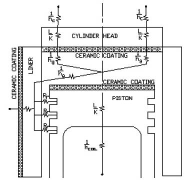
Figure 1. Wall Heat Transfer Model
Initial temperature was found by using the following expression [6].


The total conduction resistance offered by the cylinder liner, piston rings, cylinder head and piston top for the heat transfer from cylinder gases to coolant was evaluated through the following expression [6].

Initial nitric oxide formation rate was evaluated using the following equation [1].


Nitric oxide equilibrium concentration was calculated using the following equation [1].

The percent of exhaust gas recycled (% EGR) is defined as the percent of the total intake mixture, which is, recycled exhaust [1].

To validate the simulated results cylinder peak pressure was determined through experiments at identical design and operating conditions. The experimental investigations were carried in a four cylinder Conventional and LHR turbo charged direct injection diesel engine. The important specifications of the engine are summarized in Table 1.
The experimental set up is shown in Figure 2.
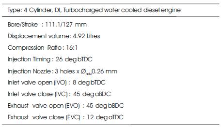
Table 1. Engine Specifications
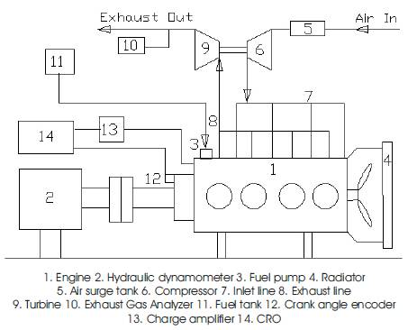
Figure 2. Experimental set up
The pressure crank angle diagram was taken using a Piezo electric pressure transducer, charge amplifier and a storage oscilloscope set up. The laboratory also had emissions testing capabilities for the engine tests. The emission set up consists of Exhaust gas analyzer for measuring NoX .
The Conventional turbo charged engine was later modified to LHR turbocharged engine by applying ceramic coating of 0.5mm thickness on piston crown top, cylinder liner outside and cylinder head inside with valves. Figures 3 and 4 show the photographic views of the coated cylinder components. The LHR turbocharged engine was later modified to LHR turbocharged extended expansion engine by late closing of the inlet valve (IVC @ 60º aBDC). Later the engine was modified to turbocharged LHR extended expansion engine with iEGR by secondary opening of the exhaust valve during suction stroke. The secondary exhaust valve opening takes place at 65º aTDC and closes at 65º bBDC. The total secondary exhaust valve opening duration is 50 degrees of Crank Angle (CA). The secondary exhaust valve lift is taken as 3mm. With this strategy, iEGR levels of 9 to 10% have been attained in the operating range of the engine.
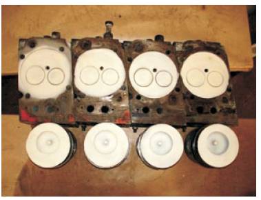
Figure 3. Photographic view of the Piston top, cylinder head inside with valves with ceramic coating
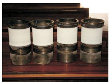
Figure 4. Photographic view of the cylinder liner with ceramic coating
Tests were conducted under the following engine conditions: 1.Conventional- Conventional turbocharged engine 2. LHR- LHR turbocharged engine 3. LHR (EEE)- LHR turbocharged extended expansion engine and 4. LHR (EEE with iEGR)- LHR turbocharged extended expansion engine with iEGR. Figures 5 to 11 shows the comparison and variation of combustion, performance and emission characteristics for the same fuel supplied (0.0696 g/cycle/cylinder) at 1500 rpm. Figure 12 shows the brake thermal efficiency for speed range of 1000 to 1500 rpm in step of 100 rpm for the same fuel supplied (0.0696 g/cycle/cylinder).
Figures 5 and 6 show the comparison between simulated and experimental values of cylinder pressure for Conventional turbocharged engine, LHR turbocharged engine, LHR turbocharged extended expansion engine and LHR turbocharged extended expansion engine with iEGR respectively. The prediction shows that the cylinder peak pressure for LHR (EEE with iEGR) is lower by about 0.89%, 5.42% and 2.67% when compared to Conventional, LHR and LHR (EEE) respectively. The increase in cylinder peak pressure for LHR turbocharged engine is mainly due to higher operating temperatures. The cylinder peak pressure of LHR turbocharged extended expansion is comparatively lesser than the LHR turbocharged engine because of the lower effective compression ratio. Also the cylinder peak pressure of LHR turbocharged extended expansion engine with internal exhaust gas recirculation is lower than the LHR turbocharged extended expansion engine and as well as LHR turbocharged engine, but it is in the operating performance limit for effective work done. The reason being for this pressure reduction is due to variation in compression ratio and charge mixing and preparation in the case of LHR turbocharged extended expansion engine with iEGR. Under identical conditions the experimental values of cylinder peak pressures as compared to theoretical predictions are higher by about 1.073% for Conventional turbocharged engine, 0.819% for LHR turbocharged engine, 0.388% for LHR turbocharged extended expansion engine and 0.891% for LHR turbocharged extended expansion engine with iEGR.
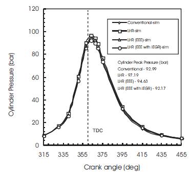
Figure 5. Comparison of Simulated values of Cylinder Pressure for conventional, LHR, LHR (EEE) and LHR (EEE with iEGR) for the diesel fuel supplied (0.0694g/cycle/cylinder) at 1500 rpm
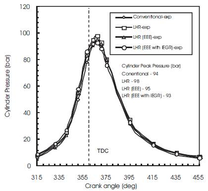
Figure 6. Comparison of Experimental values of Cylinder Pressure for conventional, LHR, LHR (EEE) and LHR (EEE with iEGR) for the diesel fuel supplied (0.0694g/cycle/cylinder) at 1500 rpm
Figure 7 shows the comparison of cylinder mean temperature. The trend shows that the LHR turbocharged engines are operating at higher temperatures. The high temperatures achieved are mainly attributed to insulation coatings applied to combustion chamber walls. The operating temperature of the LHR turbocharged extended expansion engine is lower when compared to the LHR turbocharged engine due to the lower effective compression ratio because of late intake valve closing. Because of the recirculation of the exhaust gases mainly CO2 and H2O (gaseous) the specific heat of the cylinder gases increases that decreases the operating temperature of the LHR turbocharged extended expansion engine with iEGR when compared to the LHR turbocharged extended expansion engine.
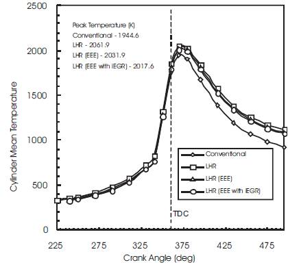
Figure 7. Comparison of Cylinder Mean Temperature for conventional, LHR, LHR (EEE) and LHR (EEE with iEGR) for the diesel fuel supplied (0.0694g/cycle/cylinder) at 1500 rpm
Figure 8 shows the comparison of rate of heat release. The trend shows that the LHR turbocharged engines are exhibiting a lower rate of peak heat release during premixed combustion. The decrease in peak heat release during premixed combustion in the case of LHR turbocharged engines is due to the decrease in delay period because of the higher operating temperatures. The peak rate of heat release during premixed combustion in the case of LHR turbocharged extended expansion engine increases compared to LHR turbocharged engine. This may be due to increase in delay period because of the lower temperature during the end of compression. The peak rate of heat release during premixed combustion in the case of LHR turbocharged extended expansion engine with iEGR increases compared to LHR turbocharged extended expansion engine due to the increase in ignition delay because of the reduction in oxygen concentration.
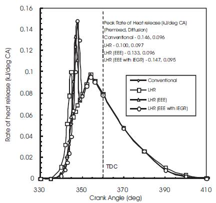
Figure 8. Comparison of Rate of Heat Release for conventional, LHR, LHR (EEE) and LHR (EEE with iEGR) for the diesel fuel supplied (0.0694g/cycle/cylinder) at 1500 rpm
Figure 9 shows the comparison of cumulative work done. The increase in the cumulative work done in the case of LHR turbocharged extended expansion engine is mainly attributed to the decrease in compression work. When compared to LHR turbocharged extended expansion engine the cumulative work done of LHR turbocharged extended expansion engine with iEGR is lesser due to lower peak pressure but it is in the operating performance limit for effective work done.
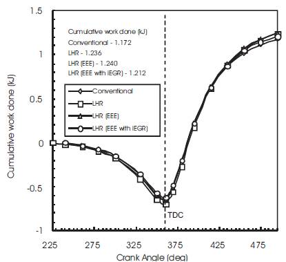
Figure 9. Comparison of Cumulative work done for conventional, LHR, LHR (EEE) and LHR (EEE with iEGR) for the diesel fuel supplied (0.0694g/cycle/cylinder) at 1500 rpm
Figure 10 shows the comparison of total heat transfer. The total heat transfer reduces for LHR turbocharged engine when compared to the Conventional turbocharged engine. This is because of the insulation coatings applied on the cylinder components. The total heat transfer is lesser in the case of LHR turbocharged extended expansion engine with iEGR because of the ceramic coating and reduced temperature difference.
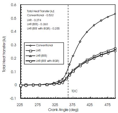
Figure 10. Comparison of Total heat transfer for conventional, LHR, LHR (EEE) and LHR (EEE with iEGR) for the diesel fuel supplied (0.0694g/cycle/cylinder) at 1500 rpm
Figure 11 shows the comparison of Nitric oxide concentration. The trend shows that the LHR turbocharged engines are producing higher nitric oxide concentration. The increase in nitric oxide concentration in the case of LHR turbocharged engine is because of the higher peak cylinder temperature. The decrease in the nitric oxide concentration in the case of LHR turbocharged extended expansion engine with iEGR is due to its lower operating temperature and lesser oxygen concentration.
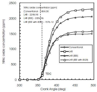
Figure 11. Comparison of Nitric oxide concentration for conventional, LHR, LHR (EEE) and LHR (EEE with iEGR) for the diesel fuel supplied (0.0694g/cycle/cylinder) at 1500 rpm
Figure 12 shows the comparison of experimental and simulated brake thermal efficiency under identical conditions for Conventional turbocharged engine, LHR turbocharged engine, LHR turbocharged extended expansion engine and LHR turbocharged extended expansion engine with iEGR. For the LHR turbocharged extended expansion engine, the increase in brake thermal efficiency of 4.94%, 4.78%, 4.66%, 4.37%, 3.78% and 4.82% at 1000 rpm, 1100 rpm, 1200 rpm, 1300 rpm, 1400 rpm and 1500 rpm respectively as compared to that of LHR turbocharged engine are predicted by simulation. Under identical conditions the experimental values are of 5.48%, 5.56%, 4.98%, 4.27%, 4.09% and 4.84% respectively. The brake thermal efficiency of LHR turbocharged extended expansion engine is higher than the LHR turbocharged engine because of the lower compression work and lesser friction.
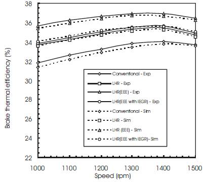
Figure 12. Comparison of Experimental and Simulated Brake thermal efficiency for conventional, LHR, LHR (EEE) and LHR (EEE with iEGR) for the diesel fuel supplied (0.0694 g/cycle/cylinder
After a detailed analysis of the Conventional turbocharged engine, LHR turbocharged engine, LHR turbocharged extended expansion engine and LHR turbocharged extended expansion engine with iEGR, focusing on combustion, performance and emission the following conclusions were made.
| A n | Nozzle hole area (m2) |
| a | Annand's heat transfer coefficient |
| act | Activation energy |
| B | Bore diameter (m) |
| b | Annand's heat transfer coefficient |
| CD | Coefficient of discharge of injector nozzle |
| c | Annand's heat transfer coefficient |
| dn | Nozzle hole diameter (mm) |
| h | Number of nozzle holes in injector nozzle |
| hc | Wall coolant heat transfer coefficient (kJ/m2hrK) |
| hg | Gas - wall heat transfer coefficient (kJ/m2-hr-K) |
| K | Constant in preparation rate equation |
| K1 | Constant in reaction rate equation |
| kc | Thermal conductivity of ceramic material (W/m-K) |
| ks | Thermal conductivity of skirt material (W/m-K) |
| kl | Thermal conductivity of liner material (W/m-K) |
| kp | Thermal conductivity of piston material (W/m-K) |
| kr | Thermal conductivity of ring material (W/m-K) |
| L | Constants |
| L | Stroke length (m) |
| lC | Connecting rod length (m) |
| li | Cylinder liner height (m) |
| M | Mass of fuel injected (grams/cycle/cylinder) |
| Mi | Total mass of fuel injected in the cylinder upto the time of injection (kg) |
| Mu | Part of the fuel still available for preparation (kg) |
| mEGR | Mass of exhaust gas recycled (kg) |
| mf | Mass of fuel injected (kg) |
| mi | Total intake mixture (kg) |
| N | Engine speed (rpm) |
| [N2]e | Equilibrium nitrogen concentration (moles/cm3) |
| [NO] | Nitric oxide concentration (moles/cm3) |
| [NO]e | Equilibrium nitrogen oxide concentration (moles/cm3) |
| [O2 ]e | Equilibrium oxygen concentration (moles/cm3) |
| P | Cylinder Pressure (bar) |
| Pi | Injection period (degree crank angle) |
| Po2 | Partial pressure of oxygen (bar) |
| Pr | Preparation rate (kg per degree crank angle) |
| Q | Total Heat transfer (kJ) |
| Qvs | Lower heating value (kJ/kg) |
| Qw | Wall Heat transfer (kJ) |
| R | Characterestic gas constant (kJ/kg-K) |
| Rc | Total conductive resistance |
| Re | Reynolds number |
| Rr | Reaction rate (kg per degree crank angle) |
| R1 R2 R3 | are constants |
| r1,r2 ,r3, r4,r5,r7,r8,r9 | Radii of the composite cylinder wall with respect to cylinder axis (m) |
| T | Cylinder Temperature (K) |
| TC | Cylinder mean temperature (K) |
| Tp | Thickness of the piston crown (m) |
| Tw | Cylinder wall temperature (K) |
| Tg | Gas temperature[K] |
| x | Constant |
| z | Constant |
| [ ] | denotes species concentration (moles/cm3) |
| ρf | Density of fuel (kg/m3) |
| θ | Crank angle (degree) |
| Δθ | Nozzle open period in crank angle degrees |
| ΔP | Pressure drop across the nozzle |
| CA | Crank Angle |
| BDC | Bottom Dead Centre |
| DI | Direct Injection |
| EGR | Exhaust Gas Recirculation |
| Exp | Experimental |
| IEGR | Internal Exhaust Gas Recirculation |
| LHR | Low Heat Rejection |
| PSZ | Partially Stabilized Zirconia |
| Sim | Simulation |
| TDC | Top Dead Centre |