(1)
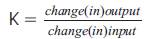
On-line tool wear estimation in turning is essential for on-line cutting process optimization. In this work, cutting force measurement is used for a reliable on-line flank wear estimation and tool life monitoring. Models for flank wear will be obtained as a function of machining parameters and dynamic cutting forces. The coefficients for flank wear models are obtained by using the experimental results. Then the non-linear dynamic models obtained are calibrated with the actual conditions. These developed models will be used for the simulation of flank wear and using control variable such as cutting speed; the flank wear will be controlled. For model validation, the flank wear is estimated using a non-linear model. In the present work, an attempt has been made to control the flank wear during turning of on-line cutting process using the Neural network based on self-tuning of PID controller approaches. This approach treats the material as dynamic system and involves developing state space models from available material behavior model.
The evaluation of performance criteria can be compared for both approaches of PI controller and Neural network based on self-tuning of PID controller. Simulation studies are carried-out for the non-linear system using MATLAB software.
Productivity and quality in the finish turning of hardened steels can be improved by utilizing predicted performance of tools. There are many parameters such as cutting speed, feed rate and tool nose radius that are known to have a large impact on surface quality. Tool wear is an important factor directly affecting the surface quality of machined parts. The direct measurement of tool wear in real time during cutting operation is an impossible task. There are already considerable research efforts affected in modeling the correlation between the measurable variables such as cutting force, temperature and tool wear. The results show that the cutting force provides significant information about the state of machining process and tool wear.
There are four important types of wear to be considered. They are crater wear, major flank wear, minor flank wear and nose wear. All of them are important but the amount of flank wear is often used in determining the tool life. The present work includes development of mathematical model and comparison with experimental results. Some important factors like the index of diffusion, wear coefficient, the rate of increase of normal load with respect to flank wear and the hardness of tool influencing the flank wear were used as input parameters to develop the mathematical model. The developed mathematical model is used to relate the wear to the input parameters for a turning operation. The model is then used to predict the tool wear. These tool wear values were compared with the experimental flank wear values [7].
The aim of present work is to develop a model to predict flank wear and compare it with the experimental results. First step is assumption of empirical models for flank wear in terms of cutting parameters and cutting forces. Next step is experimentation. Flank wear is obtained as a function of cutting speed, feed, depth of cut and cutting forces. The proposed dynamic model contains certain constants. Evaluation of constants for the proposed dynamic model has been done. The simulation and control of flank wear and comparison of the approach controllers have been performed.
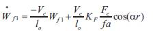
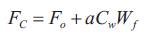
The control of flank wear in metal working processes is needed for better quality. A methodology for computations of optimal control parameters during turning process for flank wear control is proposed. This approach is based on design and implementation of conventional PI controller and Neural network based on self-tuning of PID controller through simulation. It involves developing state space models from available material behavior model. The non-linear flank wear model contains many of the important variables such as cutting force, flank wear, cutting temperature, feed, depth of cut and the cutting speed. In this model, flank wear is separated into two components: One caused by abrasion (Wf1 ) and the other by the diffusion (Wf2 ). These two components are used as state variables. The input to the process is cutting speed Vc . The model is given by the c following equations [1] & [2].
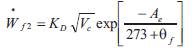
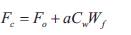
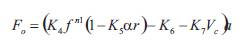
The tool wear Wf is the sum of two components of the flank wear Wf1 and Wf2 .In the above equation r is an effective rake angle; Cw ,lo ,KF ,KD ,K4 ,K5 K6 ,K7, n1 and are the model parameters, depending on the cutting conditions and tool work piece combinations. Fo is the vertical component of the initial cutting force for the sharp tool.f is the tool-work piece temperature on the flank side of the tool. An alternative way to obtain the tool-work temperature is to calculate it using an empirical relation.
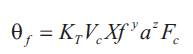
Another relation is given by,
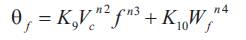
where KT ,X,y,z,K9 ,K10 ,n2 ,n3 and n4 are the model parameters, depending on the cutting conditions and tool work piece combination. The model in state variable equations are given by,
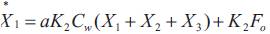


Where X1 ,X2 and X3 are the variables.

Where K0 , K1, K2, Cw and are model parameters.
The integrator provides the conversion from wear-rate to wear. The mechanically activated mechanism is represented by a first order lag with a time constant, which varies inversely with the cutting speed. The total wear Wf at any time is the sum of the wear due to the thermally activated mechanism Wf1 and the wear due to the mechanically activated mechanism, Wf2 . A step change in cutting speed is given and the open loop response for tool wear is given in Figure 1.
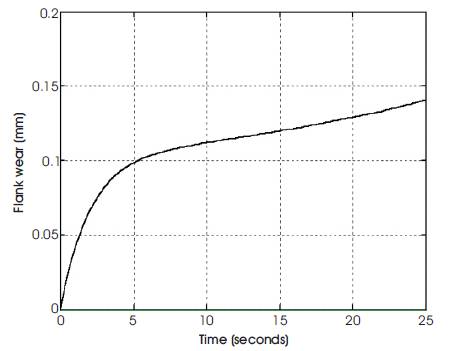
Figure 1. Open Loop Response to Estimate Controller Parameters
The transfer function for the above model is given by,
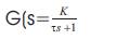
Where π=63.2% of maximum value corresponding to time axis value,
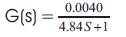
 Therefore the transfer function for the tool wear model is given by,
The function of a controller is to receive the measured process variable (pv) and to compare it with the set point (sp) so as to produce the actuating signal (m) that drives the process variable to the desired value. Thus the input to the controller is the error (sp-pv). Depending of the relation between the error and the controller output signal, controllers are classified as Proportional, Proportional + Integral (PI), Proportional +Integral + Derivative (PID) controllers [3].
Determination of the controller parameters to provide the desired response is known as controller tuning. Controller tuning can be done by using synthesis method. Design of controller by synthesis method is one of the recommended methods in process control. However the synthesis method is applicable only for open loop stable process in order to get a stable controller. Hence, the unstable process must be stabilized using a proportional controller [6].
The synthesis controller is the combination of two parts (Figure 2). The first part compensates for the process transfer function and the other is used to obtain a specified closed loop response of the controlled variable to the set point. When the process transfer function does not have dead time, the closed loop transfer function becomes,
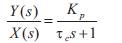
The closed loop time constant τc can be adjusted to shape the response of the loop, the smaller the τc the faster controller response. Thus τc provides a convenient parameter to reach a compromise between fast approach to set point and acceptable variations in the controller output.
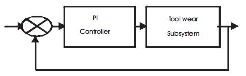
Figure 2. Block diagram of conventional PI Control System
The PI controller parameters are

From the transfer function model,
Kc = 250.985 and Ti =51.856 secs
The simulation results of PI controller for different tool wear set points changes are shown in Figures 3& 4.
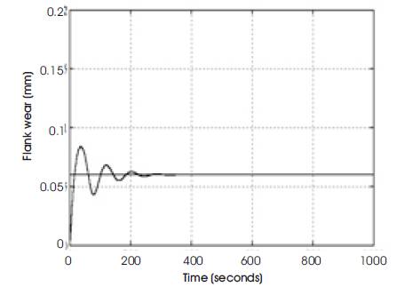
Figure 3(a). Response of Flank wear under PI controller for set point =0.06
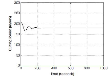
Figure 3(b). Output of PI controller for (input to the plant)
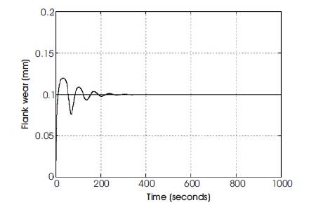
Figure 4(a). Response of Flank wear under PI controller for set point =0.1
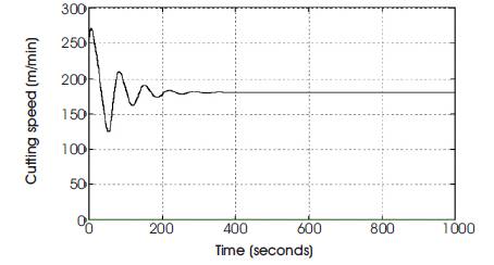
Figure 4(b). Output of PI controller (Input to the plant)
An Artificial Neural Network (ANN) is an information processing paradigm that is inspired by the way biological nervous systems, such as the brain, process information. The key element of this paradigm is the novel structure of the information processing system. It is composed of a large number of highly interconnected processing elements (neurons) working in unison to solve specific problems. An ANN is configured for a specific application, such as pattern recognition or data classification, through a learning process. Learning in biological systems involves adjustments to the synaptic connections that exist between the neurons as shown in Figure 5 [5].
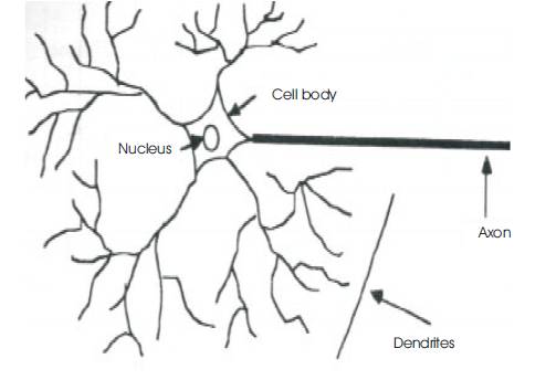
Figure 5(a). Biological Neural Network
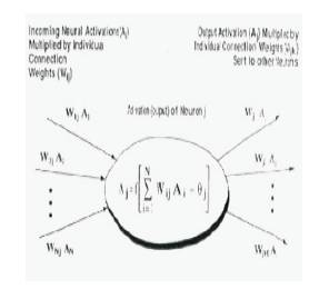
Figure 5(b). Artificial Neural Network
Fine-tuned values of PID controller parameters are used as targets for development of Neural network based on self-tuning of PID controller to generate requisite control signal depending on error signal. The three-layered neural network constructed using Matlab/Sumlink tools, Back Propagation (BP) algorithm implemented to train the network for desired targets by assigning training parameter goal to 1e-13 , which consists of an input layer, an output layer, and at least one hidden layer of nonlinear model (flank wear model) processing elements (neurons). For simplicity, the three layered BP Neural network is explained briefly here. The input-output neurons relationship of BP Neural network at the m-th layer can be described as follows:
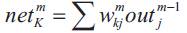
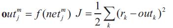
Where m is the number of layers, net k is a total input of a neuron k, out is an output of a neuron j, Wjk is the weight between neurons j and k, and sigmoid function is normally used for f (.). In the BP algorithm, to minimize the cost function j which can be expressed as follows:
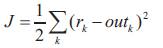
Where rk and outk are respectively, a given reference value and an out of the output layer at k-th neuron. The weights are updated by,
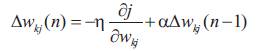
Where η>0 and α ≥ 0 are learning rate and momentum rate respectively.
The self-tuning control (STC) methods have been proposed to achieve effective, robust, and optimal method for adjusting the parameter values of some control systems [4]. Learning method is to treat the Neural networks as pattern recognition system; this proposed learning method is based on neural network self-tuning control system as shown in Figure 6. The basic idea is how to use the output error e(n)= r(n)-y(n) as a learning signal for the BP Neural network to adjust the parameters of PID controller where r(n) and y(n) are respectively, a reference value and a non-linear plant output at time(n). In the BP algorithm, the weights of the Neural network can be updated by back propagating the learning signal when the derivative can be expanded using the chain rule from equation (22), to minimize the cost function J [4].
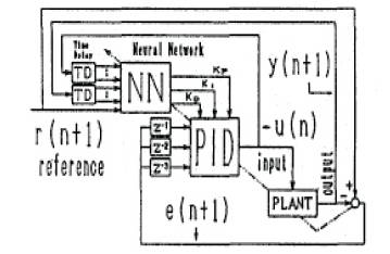
Figure 6. Self-tuning PID by Neural Network
Artificial Neural Network (ANN) improves the response obtained in the Ziegler-Nichols method. Self-tuning has considerable potential for control problems since it provides a systematic and flexible approach for dealing with uncertainties non-linearties, and time-varying parameters. Correspondingly, in recent years, the current interest has been focused on design of self-tuning controller by using NNs. In this work, a method using a BP NN is proposed to realize the real time self-tuining of adaptive NN PID controller as shown in Figure 6, through the computer simulations and some experiments to the linear and non-linear systems. Therefore, the proposed Neural network based on self-tuning of PID controller shows great advantages in real-time applications [5].
The simulation results of flank wear for various set points under neural network based on self-tuning of PID controllers are shown in Figures 7& 8.
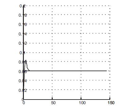
Figure 7(a). Response of Neuro PID control (S.p=0.06)
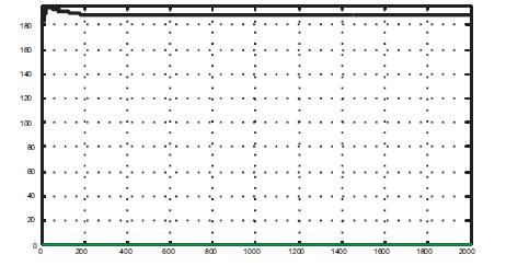
Figure 7(b). Output of Neuro PID (I/ P to the Plant)
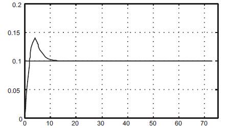
Figure 8(a). Response of NeuroPID control (S.p=0.1)
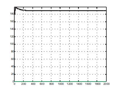
Figure 8(b). Output of Neuro PID (I/ P to the Plant)
The dynamic models developed are used for simulation. The optimization of process control parameters and process parameters are done. To optimize these parameters PI Controller and Neural network based on self-tuning of PID controller are used. In the simulation of PI Controller and Neural network based on self-tuning of PID controller, the cutting conditions are selected such that the flank wear become dominant. Such cutting conditions are obtained at high cutting speed. For a typical carbide tool and steel work piece combination, the cutting speed Vc is considered to be around 200m/min. The feed 'f' and depth of cut 'a' are chosen to be constant of 25mm/rev and 3mm respectively. In order to excite the system Vc is changed between 180m/min and 220m/min. The depth of cut 'a' is 3mm. The simulation results of PI Controller for different flank wear set points are shown in Figures 3&4. The PI controller has large number of overshoots. Also the settling time is very large for different flank wear set points.
Neural network based on self-tuning of PID controllers are defined for each controller input and output such that the three layered BP NN learning process is constant. The three layered BP NN with 4,12 and 1 neurons in the input, hidden and output layers, respectively, used for the simulation results obtained by Neural network based on self-tuning of PID controllers are shown in Figures 7 & 8. Neuro PID controller performance is better when compared to PI controller because there is an improvement in settling time and percentage of overshoot for various setpoints.
The settling times and percentage of overshoot for the both controllers are given in Table 1.
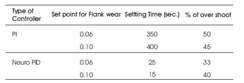
Table 1. Settling times and % of overshoot for both Controllers
This paper presents a non-linear model of tool wear which is suitable as the basis for an on-line tool wear sensing system. The model states including flank wear and dynamic state equations are developed from variable relationships in the manufacturing literature. This nonlinear state model gives qualitatively reasonable results, and analyzed about particular operating conditions. It could be developed as a neural network based self tuning PID controller which uses pattern recognition technique of nonlinear system for tool wear estimation.
The major strength of this paper is when the cutting speed is increasing gradually the flank wear also increases. From the results, it is concluded that the Neural network based on self-tuning of PID controller is the best suitable for tool wear control than PI control. Further improvement in this paper work can be done by comparing Neural network based on self-tuning of PID controller with the Neuro-Fuzzy controller for the non-linear system of tool wear control.
By comparing the responses of Neural network based on self-tuning of PID controller with PI controller it is observed that there is an improvement in settling time and percentage of overshoot. As the cutting speed is increasing gradually the flank wear also increases. From the results, it is concluded that the Neural network based on self-tuning of PID controller is the best suitable for tool wear control than PI control. Further improvement in this paper work can be compared with Neural network based on self-tuning of PID controller with the Neuro-Fuzzy contoller for the non-linear system of tool wear control.