Experimental studies have been conducted to obtain the low speed characteristics of hypersonic vehicle configuration with two different sweep back angle. The vehicle configuration consists of blunt nose, variable sweep back wing and curved fore body. The Six component force and moment data were obtained over an angle of attack range from -15 to +15 degrees on the 1: 50 scale model in the wind tunnel. The sweep back angles are also changed for different test conditions. The experimental results are presented in terms of lift coefficients, Drag coefficients and L/D ratio for various angles of attack and different flow velocities. It is found that there is positive lift coefficient for the configuration at zero angle of attack with considerable drag reduction due to the variable sweepback wings and produces high L/D ratio.
The era of practical hypersonic flight is still ahead of us and it poses many exciting challenges to the aerodynamist. On an even more ambitious scale is the concept of an aerospace plane an aircraft designed to take off horizontally from a runway and then to accelerate into orbit around the earth. It will subsequently carry out mission in the orbit, or within the outer regions of the atmosphere and then reenter the atmosphere at Mach 25, finally landing under power on a conventional runway. To attain the above mentioned performance, the hypersonic aircraft designed with blunt nose, curved fore body and variable sweepback wings as preliminary study. In this research, we attempt to summarize the low speed characteristics of variable sweep back hypersonic vehicle configuration. It is of horizontally take off and landing type vehicle, most of the lift is produced by high pressure behind the bow shock [13-16] and exerted on the relatively curved forebody of the vehicle, produces the pressure difference. The variable sweep back angle is given in such a way that the airplane during climb the wing with 34 degree sweep back angle having high aspect ratio gives good per formance on lift characteristics as mentioned by Tomcat F-14 aircraft [12].
After reaching the high speeds the wing will keep on changing its sweepback angle and at the end, the hypersonic speed, it will come up to 66 degree sweep back angle. Also at this stage it attaches towards the tail plane. This leads to attain high speed characteristics. So during the landing again it will relaxes its sweepback and come to 34 degree sweepback angle leads to landing with power.
Many researches have been done at high speeds in both experimentally and computationally [1-10]. But the low speed of this vehicle is very important because the configuration with first sweep back angle will take off and landing by low speeds. The research presented in this work initiated the conceptual design study of horizontal take off and landing hypersonic vehicle. Because the studies shown that the aerodynamic characteristics of the proposed vehicle during take off, initial climb and approach phases of the flight will greatly influence the ultimate design as reported by Robert J.Pegg [11]. An experimental investigation of hypersonic configuration on the performance at low speeds were made.
Hypersonic vehicle configuration is fabricated with teak wood to 1:50 scale. Two types of wings were fabricated with variable sweep back angle 34 degrees and 66 degrees respectively. The fore body of the model is in curved shape with nose bluntness.
The body consists of fore body, mid section and aft body. The design of the body configuration leads to various advantages for the vehicle at high speeds. The bottom portion of the fore body consists of two ramps (first ramp angle is 5 degree and the second ramp angle is 17 degree respectively from the horizontal surface).It also consists of curved bottom surface. The curvature and the ramp angles have been chosen based upon the various factors including
a) Maximizing the pressure accumulation on the bottom surface. So that the pressure difference leads to more lift.
b) To increase the inlet mach number to the engine intake.
The fore body precompresses the air and the aft body expands the flow (behaves like a nozzle). The bottom portion of the body is curve bottomed with the intent to provide more air inlet to the engine and produces more lift.
The wing is designed so as to meet the lateral acceleration requirement and from stability point of view. The body volume is more at the aft body where the fuel and the other load are kept. So the centre of gravity lies rear side of the mid section. The forebody generates more lift when compared to the other components. During the climbing of the vehicle because of lift produced by the forebody the other side wings produce counter clock wise moment to balance the airplane to fly in steady level flight condition.
At high speeds wing with more aspect ratio will not suit to attain the speed and to reduce the drag. So the sweepback concept is introduced for this type aircrafts. Also the formation of bow shock at the leading edge should not affect this wing. So sweepback at the hypersonic speed is maintained at 66 degrees. In this configuration during hypersonic speeds the mainplane attaches towards the tail plane.The models with the variable sweepback angle is as shown in the Figures1-2. So that this configuration can be used as horizontal take off and landing vehicle.
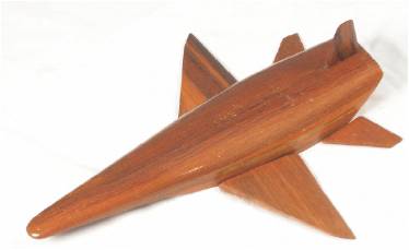
Figure 1. Experimental Hypersonic vehicle model with 34 degrees of sweep back
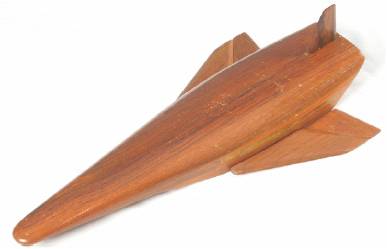
Figure 2. Experimental Hypersonic vehicle model with 66 degrees of sweep back
The wind tunnel is of 20m long tunnel and has a rectangular test section dimensions of 0.9m* 1.22m* 1.82m with a maximum speed of 89 m/s used for the experimental study is shown in Figure 4. The test section speed can be controlled by the motor with microprocessor based electronic speed control unit whose least count is 1 rpm. The tunnel is equipped with Sixcomponent strain gauge internal balance for the force measurement. The hypersonic model is fitted with Sixcomponent strain gauge internal balance and the support of the balance is fixed with the ground to avoid fluctuations due to the tunnel vibration. The outputs from strain gauges internal balance are connected to the data acquisition system with a computer interface. The strains developed on the model are realized as voltage and are converted into forces by means of standard correction factor. A careful calibration of the six component internal strain gauge balance was performed before the start of the experimental program.
The model attached with the six component strain gauge internal balance by means of metal frame shown in Figure 3.
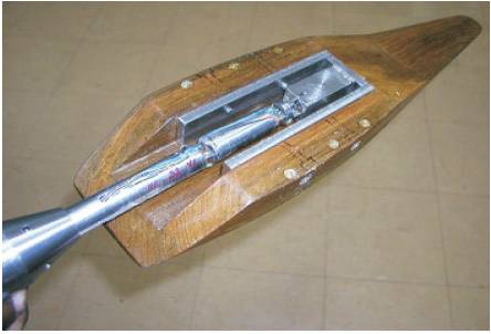
Figure 3. Strain gauge internal balance mounted in the model
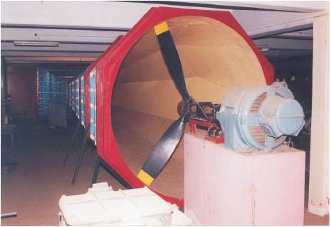
Figure 4. The Low speed wind Tunnel
Then model with the strain gauge balance mounted in the AOA change plate. The AOA change plate is mounted in the test section in such a way that they will not touch the body of the test section. And it is fixed in the tunnel to avoid vibration.The connections from the six component strain gauge balance is taken out and connected in the Data Acquisition System. The DAS has been connected to the Computer.By using the Catman 4.5 Express software the datas from the model is collected.
The AOA of the models has been changed for every test.The data collected from the balance for five speeds 9, 13, 24, 35, 43 m/s respectively. The aerodynamic forces acting on the model was measured at different angles of attack from +15 degree to -15 degree insteps of 5 degrees.
The various results obtained from the experimental analysis over the configurations shows that the body with Wing I performs well in the low speeds. According to the design body with wing I should fly at low speeds. The Figures 5-9 shows the CL Vs AOA curve in which the maximum CL obtained at 15 degree AOA. Also the CL is positive at zero AOA. Figures 10-14 shows that there is considerable drag coefficient for the configurations because of blunt nose, wing attachment etc. The L/D Vs AOA shown in the Figures14-18 gives the maximum aerodynamic efficiency occurs at 10 degree AOA.
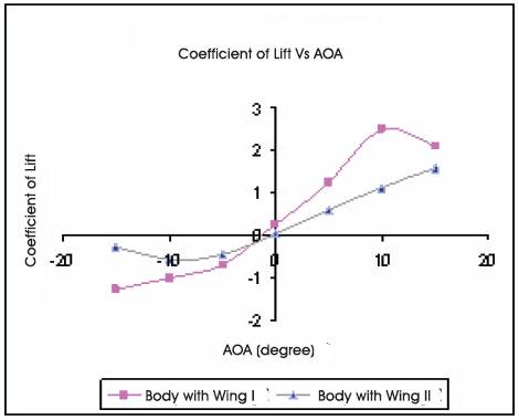
Figure 5. Variation of CL Vs AOA at 9 m/s
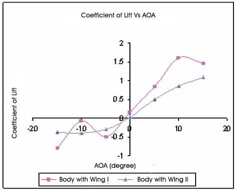
Figure 6. Variation of CL Vs AOA at 13 m/s
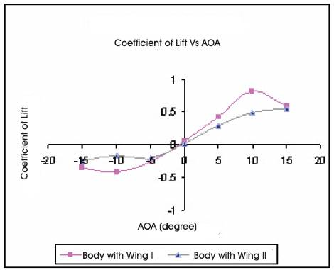
Figure 7. Variation of CL Vs AOA at 24 m/s
Figure 8. Variation of CL Vs AOA at 35 m/s
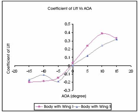
Figure 9. Variation of CL Vs AOA at 43 m/s
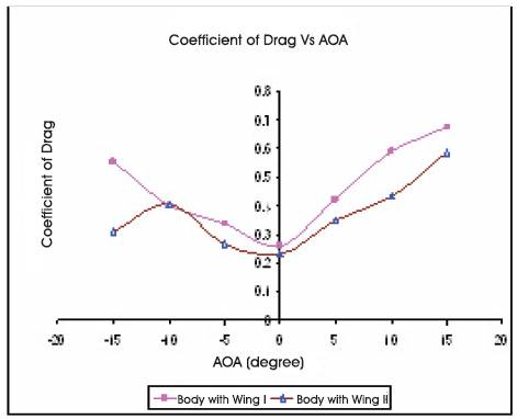
Figure 10. Variation of CD Vs AOA at 9 m/s
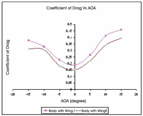
Figure11. Variation of CD Vs AOA at 13 m/s
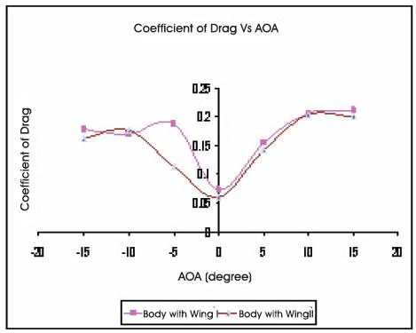
Figure 12. Variation of CD Vs AOA at 24 m/s
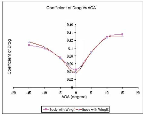
Figure 13. Variation of CD Vs AOA at 35 m/s
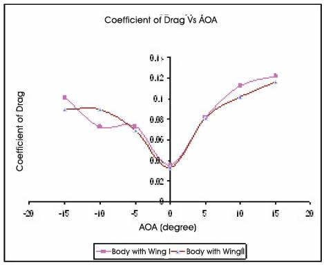
Figure14. Variation of CD Vs AOA at 43 m/s
The body with wing II shows that the stalling occurs late for this type of delta wing aircrafts. This type of configuration having low aspect ratio. But the CD Vs AOA shows that the drag is less for the body with wing II configuration. So this type of vehicle could perform well in the high speeds with less drag. The L/D ratio is maximum at the 10 degree AOA as shown in Figures15 -19. From these results the designed vehicle could perform from low speed to high speed by the concepts of curved forebody and variable sweepback wing.
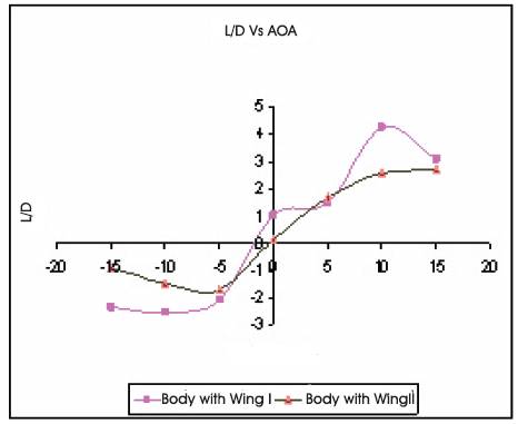
Figure.15 Variation of L/D Vs AOA at 9 m/s
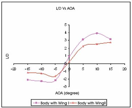
Figure16. Variation of L/D Vs AOA at 13 m/s
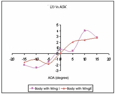
Figure 17. Variation of L/D Vs AOA at 24 m/s
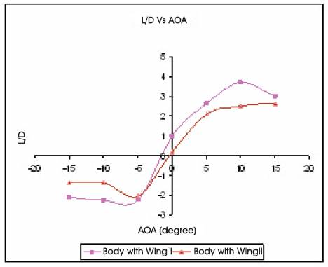
Figure 18. Variation of L/D Vs AOA at 35 m/s
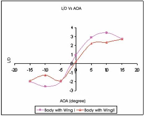
Figure 19. Variation of L/D Vs AOA at 43 m/s
In this study, the desired configuration vehicle with this design will be taking off from the ground using the sweep back angle of 34 degree and it will increase its sweep back angle to fly at higher Mach number. The vehicle with blunt nose configuration will produces more drag at low speeds. The L/D ratio of the vehicle is maximum for the sweep back angle of 34 degree. This is suitable for low speeds and the same configuration is not suitable for the high speeds. The continuous change in sweep back angle will help to improve the performance of the vehicle at high speeds.