Figure 1. Block Schematic of Proposed System
The autonomous vehicle is one of the challenging tasks in the automobile sector. In traditional driving, the human driver takes all control over the operation of the vehicle but in the autonomous vehicle, the human driver does not have any control, instead the control is with the real-time decision making computer. For the autonomous vehicle, path planning and the perception of the obstacles are very important. In the proposed work, the algorithms for path planning, object detection, and the Lane Keeping Assist system are implemented. The simulation results of all the algorithms are given in this paper.
Autonomous driving is a big challenge for all of us in the present scenario. In the automotive industry, autonomous driving is considered as a very challenging task. Some autonomous vehicles are consistent and reasonable, due to which it generates a very huge societal influence. In the autonomous vehicle, the expectations of the people are reduced in on-road mortalities, a sturdier traffic movement, saving of fuel and toxic productions, and increase passenger experience. An autonomous vehicle is very useful for the environment as it is expected to observe the route, traffic on the road and observe the traffic rules, and respond accordingly.
Various types of autonomous cars are available in the market. These cars are capable of operating without human beings and also capable of sensing the changes in the surrounding. In the autonomous vehicle, the human driver is not required to be present in the vehicle, and no need to take control over the vehicle. An autonomous car works similar to a traditional car. The algorithms, different sensors, machine learning systems, different processors, actuators, and required software to execute complex algorithms are a part of autonomous vehicles. In traditional cars, human drivers their perception of the road based on their visual sense and visibility to observe the road they drive. In autonomous vehicle research, obtaining a perception of the environment is a challenging task for engineers. Defense Advanced Research Projects Agency (DARPA), funded by the United Stated Department of Defense has conducted several prized challenges to promote research on autonomous ground vehicles. The outcome of the DARP challenges shows that sensors play a very important role because the perception stage is dependent on the active sensors. The environmental perception is created by the LiDAR (Light Detection and Ranging) and it is a 3D view of the environment. The LiDARs are used to detect the obstacles, and to detect the accurate GPS position of the vehicle is on the 2D road map. Sensors used in the vehicles provide the textureless 3D route for planning the navigation. During practice, semantic information is required for this planning different types of obstacles to account for their typical dynamics. Secondly, it has to respect the traffic rules required for the state of regulatory traffic elements. The cameras and computer vision algorithms are used to extract this semantic information. Accordingly, most of the autonomous vehicle models are integrated with different cameras and stereo rigs for perfecting the 3D information.
The software is used to process inputs from all sensors; paths are plot using software and then it sends instruction commands to the actuators of the car. Then the actuator controls the driving parameters (acceleration, steering, and braking) of the vehicle. For the autonomous vehicle, it is very important to follow the traffic rules and obstacles. The implemented algorithms in the proposed work help the software to follow required responses on the road.
In the proposed work, the various algorithms are implemented.
Many methodologies have been proposed for autonomous vehicles. Huang (2010) proposed an algorithm to detect lanes and their geometric information. The proposed work utilizes information from sensors. The paper mentioned that detection and estimation of different properties of road network settings are very difficult in real-time tasks. Also, it is very difficult to get accurate data using artificial intelligence techniques. Limitation occurs on road network parts. The problem of the lane estimation can be approachable by considering the different types of road networks, preliminary conditions required for the estimation procedure.
Zakaria et al. (2016) proposed the dynamic curvature steering control design for autonomous vehicles. In this work, lateral control and longitudinal control are proposed. A controller is designed to find out the path conditions. The calculations of the dynamic curvature are used, and based on that the vehicle speed and steering wheel angle are improved.
Desheng et al. (2016) proposed initial parameters, i.e., yaw angle, the position of the vehicle and vehicle speed. In the real traffic situations all these parameters have excessive influence on the path planning and decision-making of vehicles. Also, they proposed the method to detect moving vehicles in the traffic.
Iqbal (2020) reviewed different obstacle recognition and path finding. This work updated the research developments in the past and present in the field of obstacle detection and track identification.
Penmetsa et al. (2019) documented the perceptions, expectations and influences of autonomous vehicles (AVs) on vulnerable road users (pedestrians and bicyclists) captured through interactions. It increases perceptions of safety. The results of the interaction states that people have positive attitude towards AVs, and have grater expectation on technology to solve the current challenges.
McCrae and Zakhor (2020) in their proposed work, have generated the Point Pillars model. Then modified the Point Pillars model to develop a recurrent network, using LiDER. The original Point Pillar model uses 10 LiDER frames and the modified model used 3 LiDER frames. Modified models obtained good results for pedestrian and vehicle detection.
Rangesh and Trivedi (2019) proposed a modified MDP framework for multi-object tracking (MOT) and used multiple cameras to track objects. In the generated framework, objects of interest are tracked using techniques that are much different from old techniques.
Sung et al. (2018) worked on a greater detail with the logged driving data driving data that has been recorded in the in autonomous vehicle. The collected vehicle data is utilized to pinpoint the source of system malfunctions or unwanted operations. The stored driving data from the log can be utilized for a variety of purposes, including problem analysis, autonomous driving system research, and accident risk analysis.
Wang et al. (2013) proposed work on a quadrotor unmanned aerial vehicle (UAV) autopilot system designed using a digital signal processor as the on-board microcontroller unit. The technology and software for the UAV's autonomous flight control are also being developed. The inner loop and outer loop control methods are used to create the control algorithm.
Changhao et al. (2020) proposed a new way to solve local motion planning problems for autonomous vehicles. The authors chose time step of the vehicle state and fitted it into clothoid trajectory using dynamic programming and created a smooth trajectory, thereby eliminated several primitive and trajectory parameters.
Choi et al. (2009) designed an autonomous platoon driving system to be installed in electric vehicle which will sense the magnetic field from the installed power distribution lines under the roads to steer the vehicle. Yang et al. (2016) developed autonomous platoon driving system installed on electric vehicles and its performance has been proven through analytical and experimental testing.
An automatic driving algorithm constituted of integrated navigation and guidance control is presented to meet the demand of autonomous driving of outdoor unmanned vehicles (Yuet al., 2019). The IMU, GNSS receiver, and odometer are all part of the integrated navigation algorithm. The guidance control algorithm breaks the anticipated route into segments and determines the lateral and angular deviation between the unmanned vehicle and the segmented route.
Xiong et al. (2010) developed a novel curve tracking strategy based on preview and curve bisector for complex paths such as U-turn. The Haar feature and the Ada Boost algorithm are used to train and obtain traffic light classifiers for recognizing traffic lights. To complete the verification, each candidate region is normalized in RGB and HSV spaces and compared to a threshold.
By merging human input with automatic supported control based on potential method and virtual impedance control, a driver aid system that is not substantially reliant on sensor accuracy was proposed by Sakai and Murakami, (2016). Steer-by-wire technology is integrated into the car's steering wheel to enable vehicle tele-operation and aided control.
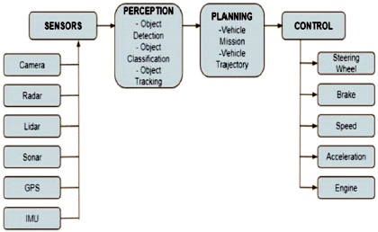
The block schematic of the proposed work is shown in Figure 1. The sensors are used to sense the changes in the world. A number of sensors are mounted at different points on the vehicle. In the perception block, data from the sensor is processed and the meaningful information is found.
Figure 1. Block Schematic of Proposed System
The planning system uses the information from the perception block for path planning. It includes short and long-range path planning. The planning block provides the correct path for the control block. The control block checks that the vehicle follows the correct path and sends the control command to the vehicle.
The flow chart of the proposed system is shown in Figure 2. The methodology is divided into three parts as shown in Figure 2.
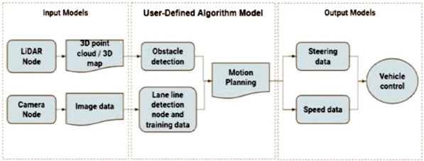
Figure 2. Flow Chart
The input model includes the sensors used in the system. In the proposed system, the sensors are camera, radar, and LiDAR. The camera and other modules are used to visualize the car surroundings and helps to determine the speed and distance of nearby objects. Also, it detects the three Type equation here.dimensional shape of the object. The cameras are mounted on every side of the car or vehicle, i.e., left, right, front, and rear. They are stitched together to obtain the 360- degree view of the surrounding environment. Some cameras have 120 degrees of field view and shorter range. The second focus is on the narrow view of the environment to provide long-range objects or views. The camera provided accurate visuals but still, they have some limitations. They can easily separate details of the adjacent visuals. To know what the location of an object is, it needs to calculate the distance of the objects or obstacles. Sensors are used to spot surrounding objects like cars under low visibility conditions, as in the case of a distant object in fog or moving cars in the rain or darkness. The radar sensors can be useful in a low visibility environment. Radar sensors can easily enhance the camera vision in low visibility mode for autonomous vehicles. Radar can predict the speed and location of the moving object and hence radar sensors are placed around the vehicle. The radar and camera around the vehicle can acquire data adequate for the autonomy at a lower level; it may not cover all circumstances without a human driver. In the proposed work, the LiDAR is placed around the autonomous vehicle, to have 3D view of the surrounding with the road geography along with the shapes and depths of objects including pedestrians. LiDAR sensors are capable to generate detailed 3D image instantaneously aided by invisible laser beams. The 3D images generate "point clouds" for vehicles on road viz., car, buses, van, trucks, etc. to improve safety on road. Though LiDAR is a useful, it can be used at key places in the vehicle as they cost 10 times the cost of camera and radar put together. Moreover, LiDAR have limited range of sensing ability.
For the autonomous vehicle, perception of obstacle detection and tracking the objects in the surrounding are important tasks. Path planning and decision-making can be done based on this content. The algorithm uses the inputs from the sensors to perform the obstacle detection and lane detection operations.
The first important features of autonomous vehicles are to detect objects correctly and accurately. The second important feature is to track the lane of the vehicle. The autonomous vehicle should avoid collision. The vehicle should have the capability to identify and distinguish the existence of a hindrance or obstacle precisely, on time so that the vehicle can stop at a safe distance and avoid collision.
Likewise, in the autonomous vehicle, the detection of the track is a highly essential as the vehicle has to travel within the boundaries of track. The vehicle must follow the lane order and road regulations.
In the proposed work this is a control module. It has the control units to control the steering, accelerator and brake pedal, mechanical systems of the car. In the conventional vehicle, the driver decides the path and steer the vehicle manually with the preview available through the windscreen and controls the steering wheel and speed according to the deviations, obstacles and traffic flow. In the autonomous vehicles the steering system is controlled by a decision making system according the programmed path. The deviation is kept small in the proposed work using feedback control using motorized steering wheel. The data of the CCD camera is used to calculate the reference trajectory. On the other hand, data of GPS or a gyroscope is used to derive the compensation scheme. The lateral deviation and yaw angle are needed to be calculated for the vehicle. The system consists of a camera sensor that measures the lateral deviation and relative yaw angle. The camera sensor measures parameters, i.e., curvature and its derivatives.
The vehicle is equipped with adaptive cruise control (ACC). It consists of a radar sensor that calculates the distance to the preceding vehicle or automobile in the same lane.
The ACC system works in the speed control mode and spacing control mode. In speed control, the vehicle travels at a driver-set speed and in the spacing control mode, the vehicle keeps a safe distance. The selection of modes is decided by the ACC system and it is based on real-time radar measurements. The ACC system switches between two modes depending on the radar measurements. If the lead car is found very close then the ACC system has to switch from speed control into space control. Likewise, if a lead car is found at a far distance then the ACC system has to shift from space control to speed control. In other words, we can say that the ACC system allows the car to travel at a driver-set speed unless and until it does not break the safe distance boundaries.
Several algorithms are implemented in the proposed work. The algorithm for the LiDAR Point Cloud Map, LiDAR radar fusion, Lane Keeping Assist and Adaptive Cruise Control are implemented. In this section, the simulated results are shown for the implemented algorithms.
The algorithm for the LiDAR Point Cloud Map is shown in Figure 3. In the LiDAR Point Cloud Map algorithm, firstly the driving scenario is developed.
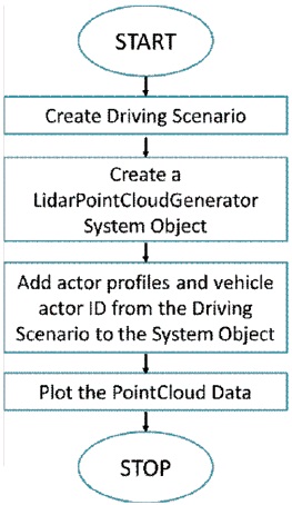
Figure 3. LiDAR Point Cloud Map Algorithm
After that, the LiDAR Point Cloud Generator system object is created. Then profiles and vehicle actor ID from the driving situation to the system object has been added. Finally, the system plots the point cloud data. The simulation results of the algorithms are shown in Figure 4 and Figure 5. Figure 4 shows the driving scenario and Figure 5 shows the LiDAR Point Cloud Map.
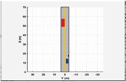
Figure 4. LiDAR Point Cloud Map: Driving Scenario
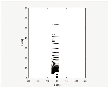
Figure 5. LiDAR Point Cloud Map
The algorithm for LiDAR radar fusion is shown in Figure 6. The 2D and 3D radars are used in the algorithm to view the surrounding environments as explained. To detect the cluster bounding box, the bonding box detector is used and a conventional JPDA tracker tracks the 3D cuboids. The output of the extended object tracker is 2D rectangular tracks, and the output of JPDA tracker is 3D cuboid tracks. These two outputs are inputs to the track-level fusion. Finally, the 3D cuboid tracks are generated.
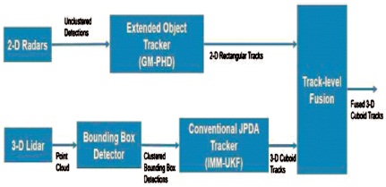
Figure 6. LiDAR Radar Fusion Algorithm
The simulation results of the LiDAR radar fusion algorithm are shown in Figure 7. In Figure 7, the front view and the rear view are observed. The LiDAR and Radar output also can be observed.
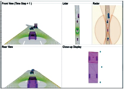
Figure 7. LiDAR Radar Fusion Simulation
The Lane Keeping Assist simulator diagram is shown in Figure 8.
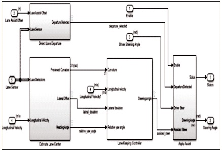
Figure 8. Lane Keeping Assist Algorithm
The simulation results of the Lane Keeping Assist system are shown in Figure 9.
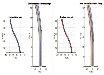
Figure 9. Outputs of Lane Keeping Assist Simulation
The algorithm for the adaptive cruise control system is shown in Figure 10. The algorithm consists of specifications of the model of the vehicle. Then specify the initial parameters of the vehicle and default gap parameters. Acceleration, velocity, and distance between two cars parameters are considered in the algorithm. The next step of an algorithm considered physical limitations and constraints to get the final output.
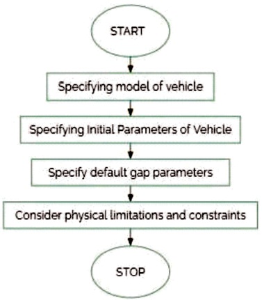
Figure 10. The Adaptive Cruise Control Algorithm
The simulation results of the adaptive cruise control algorithm are shown in Figure 11. The variation in acceleration, velocity is observed in the results.
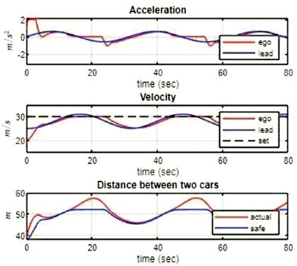
Figure 11. Output of Adaptive Cruise Control Algorithm Simulation
The proposed work used a LiDAR Point Cloud Generator System object to generate LiDAR Point Cloud data. Data is used for a driving scenario with multiple actors. Object level signals from radar and LiDAR sensor are generated and fused using a track-level fusion scheme, to visualize the scenario of the driver. The Lane Keeping Assist keeps the autonomous vehicle on the track by adjusting the steering wheel with lateral deviation and relative yaw angle close to zero. In the proposed work, the controller always keeps the distance between the two vehicles at a greater distance defined as safe. When the distance is larger, the autonomous vehicle increases it speed to a maximum as defined according to road safety norms. The proposed work successfully simulated the algorithms for the autonomous vehicle and obtained good results for the implemented algorithms.