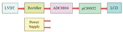
Figure 1. Block Diagram of the Proposed System Under Investigation
This paper deals with the development of an embedded system to measure the linear displacement deploying electromechanical transducer, LVDT (Linear Variable Differential Transformer). On survey it is found that linear displacement measurement have key applications in Instrumentation and Testing, Process and Packaging, Automation, Robotics, Suspension Measurement and Monitoring, Machine Presses, etc. Moreover, in such domain this displacement is in micrometer range. Hence, easy, immediate and preciseness in digital readout is quite essential for further processing or decision making. Therefore, microcontroller MCS-51 series based system is developed to measure the linear displacement, emphasizing the LVDT transducer developed in the laboratory to sense mechanical motion or vibrations. The developed LVDT transducer is interfaced through the microcontroller AT89S52, which has promising features like lowpower, high-performance CMOS 8-bit, In-System Programmable (ISP) Flash memory, etc. The data acquisition system (DAS) DAS is developed utilizing operational amplifier TLC 271 and ADC 0804. The smart LCD module, 16 x 2, is interfaced to AT89S52 for digital read out. The Kiel Vision3, IDE, is utilized to develop firmware in embedded C. The system under investigation is calibrated to scientific unit and tested.
Nowadays, the smart instrument systems are needed for the growing industrial control systems. Wherein, the advanced technologies like, Embedded, PLC system, etc., overcomes the drawbacks of traditional manual observation and measurement system (Kanchi & Gosala, 2010). The advanced technologies support precise physical, chemical parameters monitoring, manipulation and controlling industrial operations. The smart sensors also play key role to sense the parameter and convert it in to electric signal. A typical embedded system consists of computing device along with other analog and digital parts. It includes the data acquisition system, data processing system and a system for the data storing as well. The embedded system also includes communication protocols and the devices for signal sensing and actuation. An important feature is that it can work standalone to cater the need of dedicated applications. In short the sophisticated instrumentation like embedded system is playing key role in scientific analysis of performance of various physical parameters. On observation, it is found that the electromechanical parameter monitoring and controlling is challenging task to the researchers (Taksande & Bagdi, 2016). It requires suitable sensors, signal conditioning system, signal processing unit and indication unit.
On literature survey it is found that the different types of monitoring and controlling systems are available for chemical parameters. However, physical parameters like displacement, angular displacement, etc. are rarely discussed. Considering this challenges into account for industrial sector, it is proposed to design and develop a microcontroller based system for displacement monitoring deploying Linear Variable Displacement Transducer (LVDT). To meet the desired aim of the proposed system, the LVDT is wired with the microcontroller. The LVDT works with the principle of mutual inductance (Nyce, 2004).
In the present research work, more emphasis has been given on development of displacement monitoring system deploying Linear Variable Displacement Transducer (LVDT) and its interface to microcontroller 89S52. The system design uses a microcontroller based embedded system for measurement of the small scale displacement (Jefriyanto et al., 2020). It consists of designing hardware as well as software for the embedded system.
Entire system at a glance is depicted by means of block diagram as shown in Figure 1. The system consists of various electronic parts along with microcontroller to satisfy the need of embedded system. As presented in the Figure 1, the hardware consists of the LVDT, signal conditioner, microcontroller, display and power supply unit. All discreet components are selected by using working principal and their role in system after evaluating respective datasheets. Realizing the block diagram, the system circuit diagram is developed as shown in Figure 2.
Figure 1. Block Diagram of the Proposed System Under Investigation
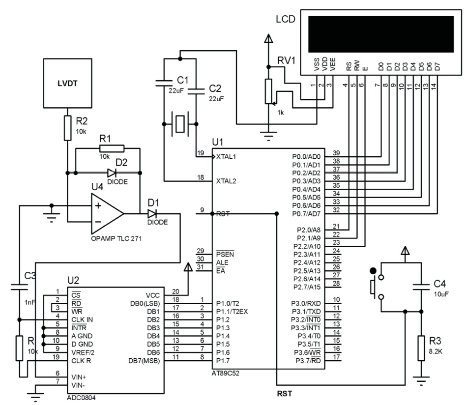
Figure 2. Circuit Schematic of the System Under Investigation
The LVDT works under the principle of mutual inductance and the displacement with which non-electrical energy is converted into electrical energy. The LVDT is made up of a cylindrical former with two secondary windings that are equal but opposite each other, i.e., if the left secondary winding is clockwise direction the right secondary winding is in anti-clockwise direction, so that the net output voltage would be the difference between the two secondary coils. The two secondary coils are represented as S1 and S2 respectively. The iron core is placed in center of the cylindrical former which can move in and out, as shown in Figure 3. For operation of LVDT, the AC excitation voltage is applied 5 volt with operating frequency of 52 - 400 Hz.
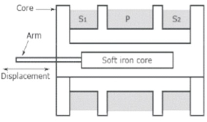
Figure 3. Construction of LVDT
The major aim of this project is to sense the analog signal convert and it to digitial for signal further processing using the microcontroller 89S52. This analog signal from the LVDT is AC. Therefore, there is need of rectification and further amplification (Weissbach et al., 2000). For this purpose precision rectifier amplifier is deployed as shown in Figure 4 (Govinda, 2015). To avoid the complexity of the design and minimize the I/O ports of the microcontroller, multichannel ADC is needed. And hence microcontroller compatible ADC 0804 from the Texas Instruments is utilized for digitization.
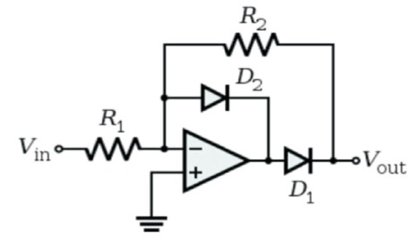
Figure 4. Precision Rectifier
The precision rectifier, also known as a super diode, is a configuration obtained with an operational amplifier in order to have the circuit to behave like an ideal diode and rectifier. It is useful for high-precision signal processing. In this case, when the input is greater than zero, D1 is OFF, and D2 is ON, so the output is zero because the other end of R2 is connected to the virtual ground and there is no current through R2. When the input is less than zero, D1 is ON, and D2 is OFF, so the output is like the input with an amplification of -R2/R1.
The ADC 0804 data acquisition component is a monolithic CMOS device with single analog channel 8-bit analog-todigital converter having microprocessor compatible control logic. The 8-bit A/D converter uses successive approximation as the conversion technique. The device eliminates the need for external zero and full-scale adjustments. Easy interfacing to microprocessors is provided by the latched and decoded multiplexer address inputs and latched TTL TRI-STATE outputs (Texas Instruments, n.d.).
The ADC0804 offers high speed, high accuracy, minimal temperature dependence, excellent long-term accuracy and repeatability, and consumes minimal power. These features make this device ideally suitable to applications from process and machine control to consumer and automotive applications. Analog to digital converter is most essential stage of the data acquisition system to translate the analog signals to digital signal so that the controller can read and process them. The variety of ADC are available having 8, 10, 12, 16, etc., bit resolution. The higher resolution ADC provides a smaller step size. Step size is the smallest change that can be recognized by an ADC. However, the ADC 0804 employed for present system is having 8 bit resolution with in built clock generator and offering continuous mode of conversion.
The research work is for monitoring small scale displacement using the embedded system. In embedded system microcontroller acts as a heart of the system. Therefore, different series of microcontrollers are studied with their variants. Different microcontrollers are available from various vendors such as Intel, Atmel, Philips, Dallas, PIC (Kumbhar & Mane-Deshmukh, 2018), AVR, ARM, etc. Out of available series of microcontrollers from Intel and Atmel the 89C51 and 89C52 are fundamental having 4 kB and 8 kB flash program memory respectively. However, these microcontrollers do not have in circuit programming (ISP) facility. For sophisticated microcontroller ISP is essential. The microcontroller 89S52 is from Philips and it has ISP facility (Langhammer & Jerabek, 2013).
The 89S52 is suitable for present design due to many advantages as it supports 8 bit processing core, designed using HMOS technology (Tilekar et al., 2017). It supports in system programming (ISP) facility. Two lines Tx and Rx from port 3 are used for serial programming. The 89S52 have 128 byte internal RAM and we have access to 64 kB for program and 64 kB data for external memory. The 89S52 operate on single 5 volt power supply and operating frequency is 12 MHz.
To display the result of data processing, the output device is required. The smart LCD from Hitachi as shown in Figure 5 which is used in this work. The traditional LCD requires complex hardware such as character generator, display refreshing circuitry etc. and complexity in software as well. To overcome this problem Hitachi produced the smart LCD (HD 44780), wherein all these components are included. The word smart means device is intellectual. The LCD used in this project to display particular characters consists of 8 pins for data lines (DB0-DB7), three pins for power supply and three pins for control signals.
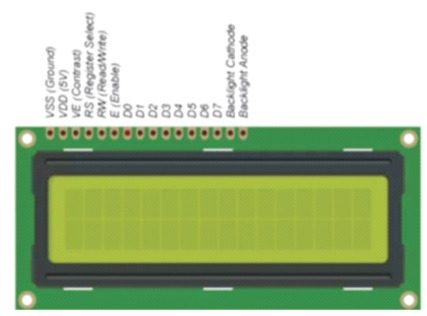
Figure 5. Liquid Crystal Display
To display letter or number from A-Z or a-z and 0-9, we should send corresponding ASCII codes to LCD through data lines. To display character it is essential to send the command for initialization of modes of the LCD. The LCD can be configured in two modes as sending command and data with the time delay and sending command and data with busy flag checking.
In time delay mode, a delay of particular time is produced by the introduction of delay subroutine. For this purpose, the timers available in the microcontroller could be used. Time delay subroutine could be called within two successive command or data fetch operation. The delay time produced should be proper otherwise interference of data may take place. This mode has been used to display the set of characters. The LCD used is 16 x 2 lines. Therefore, 16 characters could be displayed on one line and 16 characters on the second line.
Moreover, the LCD can also be interfaced by using only four data lines. During this configuration the LCD must be configured accordingly. It adds complexity in the software. In the second mode, busy flag checking, the bit D7 of LCD is considered as a busy flag. During the character displaying the busy flag remains unaffected. The status of this flag is cheeked by polling mode, which means the microcontroller does not issue command or data till the LCD is ready.
The microcontroller needs +5 V supply. With the help of transformer 12- 0-12 V, the AC mains is step down to 12 AC. Using bridge rectifier same is converted in DC. A capacitor is used to this 12 V DC to filter it to pure DC. As the microcontroller needs regulated +5 V supply, it is designed using IC 7805, which is shown in Figure 6.
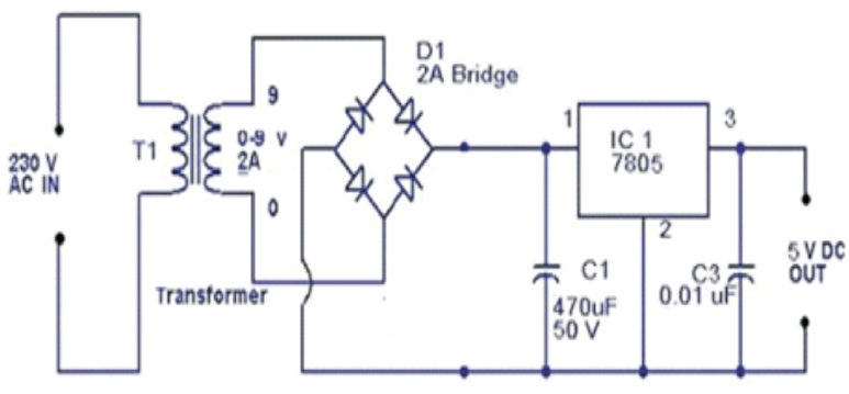
Figure 6. Power Supply Designed for the System
Developing software for microcontrollers based systems involves the use of wide range of tools, which includes editors, assemblers, compilers, debuggers, simulators, emulators, ISP, OCP, etc. To place these entire components together nowadays, the sophisticated integrated development tools (IDE) are available. For present system the Keil mVision4 IDE is utilized. The flowchart of the program is shown if Figure 7. In order to solve the different goals of the embedded software, different function have been defined which could help the synchronization operation. The function defined (Deshmukh et al., 2018) and used are as listed below.
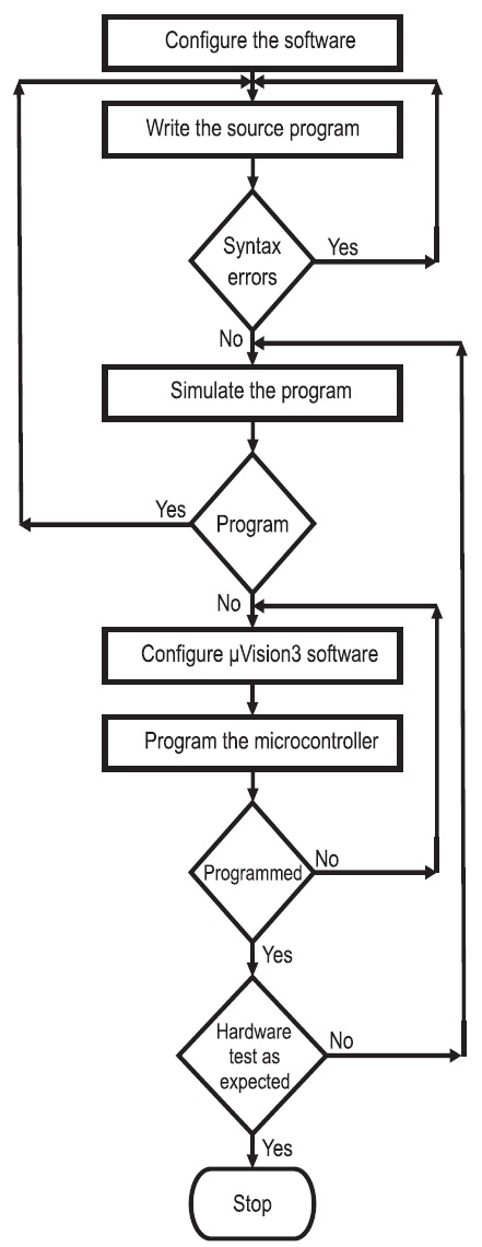
Figure 7. Design Flow for System Software
The software has been developed in embedded C programming language and flashed in program memory by using suitable IDE.
A major aim is to measure the displacement in the term of electrical signal. This is very effectively done by deploying the standard LVDT. The analog signal generated by the LVDT is digitized by using 8-Channel Multiplexer ADC for the further processing. The channel - 1 is used for this purpose. The digitized signal is processed using microcontroller 89S52 and result is interpreted and plotted as shown in Figure 8.
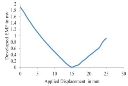
Figure 8. Graph of Developed emf with Respect to Distance in mm
The signal acquisition part of the system provides the LVDT dependent analog emf. To show this LVDT dependent emf in the terms of standard LVDT form it needs to calibrate the system. The system is calibrated against the standard meter. For the developed system and standard meter is simultaneously exposed to the LVDT system. For this physical displacement is carried out at core of LVDT with respect to micrometer screw gauge, the resultant emf is developed in AC form. Using signal conditioning the same is rectified and monitored on LCD which is connected to the microcontroller. All tasks are supervised through the developed embedded firmware. After monitoring the emf with respect to screw gauge, data is plotted and shown in Figure 8. As the principle of LVDT, when core is at center position the developed emf is near about zero called residual voltage due to winding capacitance and variances in magnetic material. When it is increasing and decreasing respectively with the position of core, emf changes respectively. However, the aim of present research work is to monitor small change in displacement using the LVDT. Hence, for present research work we only consider half part of reading that is from 0 to 15 mm. Using this we plot the graph and we derived the empirical equation for the curve as shown in Figure 9. Deploying the empirical equation in the system software, the system is ready for practical implementation.
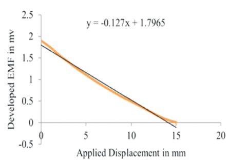
Figure 9. Empirical Equation for Developed emf with Respect to Distance in mm
Emphasizing the microcontroller based technology, the research work is undertaken and the displacement measurement system is designed. For this work the 89S52 microcontroller is used. As per that the proposed system is developed for measurement of LVDT. The necessary DAS is integrated around the microcontroller. The prototype of the system is shown in Figure 10. After calibration the system it is ready for practical implementation. As shown in figure when the mechanical displacement occurs then the position of core changes which develops an emf with respect to applied displacement. The developed emf is processed by using microcontroller and displays the real unit data on the smart LCD. The system output and the applied displacement is plotted as shown in Figure 11, which indicates the system is designed successfully for the desired aim.
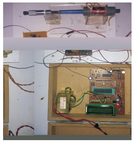
Figure 10. The Prototype of the System Under Investigation
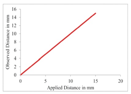
Figure 11. The Graph of Applied Displacement with Respect to System Output
A microcontroller based embedded system is designed for measurement of the displacement employing the principled semiconductor transducer. The LVDT provides the voltage in mV. Using Atmel 89S52 microcontroller the system is developed. To minimize the hardware of the system 8-Channel Multiplexer ADC 0804 is employed. Deploying the IDE, Keil Vision4, the necessary firmware is developed and embedded in the microcontroller using ISP tool, PROGISP Ver 1.72.
The LVDT observations shown by the system under the investigation by the transducer is highly reliable and precise. On inspection of the result, it can be concluded that the present system works successfully. This reveals the correctness, reliability and successful design of the embedded system using the microcontroller based technology.
The system output is monitored on LCD which can be transmitted at remote location through wireless connectivity or IoT.