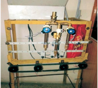
Figure 1. PLC Based Water Bottle Filling Project
This paper presents a small plant of the water bottle filling, capping and labelling machine, and states the comparison between same projects using different controllers such as PLC, ARM7 controller, 8051 controller. A large number of bottles can be filled simultaneously using PLC (Programmable Logic Control). At the same time, a project using 8051 or 89C51 controller takes more time to perform the same task and it only fills one bottle at a time. The aim of the project is to develop an automatic machine for bottle filling, capping, and labelling to reduce labor. It is performed with superior performance using ARM7 controller. The project stated in this paper uses a conveyor belt, which is controlled by an ARM7 processor, which manually places the bottle on the conveyor to move forward to fill with water. The graphical display indicates the quantity of water filled in bottles and the number of bottles filled. In capping section, a robotic arm is used to fix the cap on bottle using DC motor. In next step, the bottle gets labelled on running conveyor belt. The software used is the embedded C programming, which guides the ARM7 processor to perform the respective tasks. The conveyor belt is controlled with the ARM7 processor using IC LPC2148.
This project is made for automation in industries with easy programming and maintenance. The objective of the project is to make an automatic machine for bottle filling, capping, labelling to reduce labour. As labour reduced, human errors are decreased (stopped) and the production rate and speed is increased. Furthermore, the production time is reduced. The paper presents the description of actual project performed based on ARM7 controller, which is compared with the project based on PLC which does work speedily compared to other methods. Using PLC (Programmable Logic control), more number of bottles can be filled at same time. Same project is also compared with project using controller 8051, which takes more time to perform and fills only one bottle at a time.
The project stated in this paper uses a conveyer belt, which is controlled by an ARM7 processor, which manually places the bottle on the conveyor to move forward to fill with water. The graphical display indicates the quantity of water filled in bottles and the number of bottles filled. In capping section, a robotic arm is used to fix the cap on the bottle using DC motor. In next step the bottle gets labelled on running conveyer belt. The software used is the embedded C programming which guides the ARM7 (Advance RISC machine version 7) processor to perform the respective tasks. This project is proposed for a small plant of the water bottle filling machine. In the performed project there is a conveyer belt controlled with the ARM7 processor using IC LPC2148. The same project is compared with different controllers (Electric Machine, n.d.) and the comparison is stated in this paper.
Literature survey of the project for water bottle filling is performed in which different methods are studied using the same project being done. Different results are compared by analyzing the time required, costing, speed and performance, handling etc.
Different methods include bottle filling using PLC, using microcontroller 8051, using ARM7 processor are described further in detail.
The method using PLC that invloves placing bottles on a conveyor belt and filling bottles as programming instructions. It fills a large number of bottles at a time. In a conveyor system, stepper motor is used for its efficiency. Figure 1 shows a model for bottle filling using PLC (Omron, n.d.). It includes the user defined volume selection at the desired level. The system may have a less number of sensors, so it will be less expensive. The filling is controlled by PLC (Programmable Logic Controller) using ladder logic method. In the bottle filling system, the PLC sensor gets feedback on the bottle filling system and controls the solenoid valve and conveyor belt. By programming the PLC, the entire system is being controlled. Sensor stands as the most important part for bottle filling model (Bottle Rockets, n.d.). Normally in all automation industries, PLC is considered as the heart of any system. The entire system is made more flexible, time saving and user friendly. This is the way the operation of PLC is per formed (Baladhandabany et al., 2015).
Figure 1. PLC Based Water Bottle Filling Project
The another method of bottle filling is performed using controller 8051 or it can be done using 89C51 controller. Control system implies direct interaction with physical world. Control system includes sensor and actuators, the critical pieces needed to ensure that our actuators system can help us manage our activities and environments in desired ways. The sensor implemented in this project is an infrared sensor (Bryan & Bryan, 2002).
Controller-8051 based project is shown in Figure 2. Infrared sensor is widely used in daily activities such as for security, memory detection and other purposes. Infrared sensor consists of two basic part; which are emitter and detector (Thermographic Camera, n.d.). In this project, infrared sensor is used to detect the motion of bottle. It is the bottle movement on the conveyor belt. When the infrared sensor detects the position of bottle, the motor of conveyor will stop automatically. This method is slower compared to PLC controller method, hence this method is now-a-days considered as outdated method although it is less expensive.
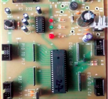
Figure 2. Project using Microcontroller
Next method we studied is using ARM7 processor LPC 2148IC. ARM machines have a 32 bit Reduced Instruction Set Computer (RISC) load store architecture. The relative simplicity of ARM machines for low power applications like mobile embedded and microcontroller applications and small microprocessors make them a lucrative choice for the manufacturers to bank on. The direct manipulation of memory is not possible in this architecture and is done through the use of registers. The instruction set may offers many conditional and other varieties of operations with the primary focus being on reducing the number of cycles per instruction featuring mostly single cycle operations (Meah et al., 2010).
The comparison between these methods states that the expenditure required for PLC is more compared to other two methods while it is least for 8051 controller. Time required for twenty bottle package filling is very less using PLC compared to other methods and it is maximum for 8051controller and moderate timing is required for ARM7 controller.
The comparison performance of project using different controllers are given in Table 1.
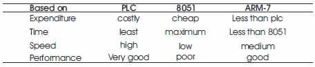
Table 1. Comparison Performance of Project Using Different Controllers
This project is proposed as a small plant of the water bottle filling machine. In this project, there is a conveyor belt, which is controlled with the ARM7 processor. A bottle is manually placed on the conveyer which will pass forward to fill the water. That filling is done by the bottle, which will indicate on the graphical display how much the bottle is filled and how much water is used. That arm processor will have a robotic arm which will take a cap of bottle and fit it neatly on to the bottle. It then passes to forward section where the bottle gets labelling the whole detail. After that, the bottles are ready to pack, then another worker will put it in the box for the sale. The software used is the embedded C programming which guides the ARM7 processor to perform the respective tasks.
The project uses ARM7 processor with LPC2148 as mentioned.
Block diagram (Figure 3) of Bottle filling plant is subdivided into few basic parts that are as follows:
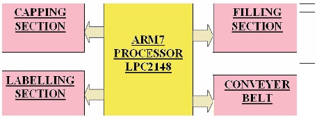
Figure 3. Block Diagram of the Project
This system consists of a ARM7, control panel, motor, and a conveyor. First the input is given to the ARM7, after that with the help of sensor, the input will be send to the control panel. The LPC2141/42/44/46/48 micro-controllers are based on a 16-bit/32-bit ARM7TDMI-S CPU (TDMI-Thumb instruction, debugger, multiplier IC) with real-time emulation and embedded trace support, that combine microcontroller with embedded high speed flash memory ranging from 32 kB to 512 kB. A 128-bit wide memory interface and unique accelerator architecture enables 32-bit code execution at the maximum clock rate. For critical code size applications, the alternative 16- bit thumb mode reduces code by more than 30% with minimal performance penalty. Due to their tiny size and low power consumption, LPC2141/42/44/46/48 are ideal for applications where miniaturization is a key requirement, such as access control and point-of-sale. Serial communication interfaces ranging from a USB 2.0 Full-speed device, multiple UARTs, SPI, SSP to IC-bus and on-chip SRAM of 8 kB up to 40 kB, make these devices very well suitable for communication gateways and protocol converters, soft modems, voice recognition and low end imaging, providing both large buffer size and high processing power. Various 32-bit timers, single or dual 10- bit ADC(s), 10-bit DAC, PWM channels and 45 fast GPIO lines with up to nine edge or level sensitive external interrupt pins make these microcontrollers suitable for industrial control and medical systems.
Structure of the project (Figure 4) contains sensors to sense the bottle which is on conveyor belt. The bottle is sensed by first sensor and water filling is started using water pump upto desired quantity as per programming. When bottle goes forward second sensor will ON, after the bottle is detected, the capping process is started using robotic arm. After that, conveyer belt move again for labelling section, then the bottle get labelled. LCD is used which shows bottle count as well as water quantity of water filled. As per the programming, all actions are performed and backup is also saved in the computer.
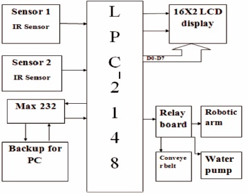
Figure 4. Block Diagram of the Structure of Project
The different steps such as filling, capping, labelling are described further.
The first step is to fill bottle for which the first sensor sense and the conveyor belt stop for particular time according to the programming instructions. When the bottle is sensed by sensor, the water pump get ON and 1litre of water is filled in bottle automatically, then again conveyer belt moves the bottle forward.
Figure 5 shows actual picture in which sensor, water pump is seen clearly and gives clear idea of water bottle filling section.
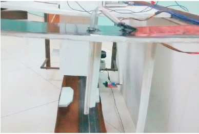
Figure 5. Bottle Filling Process
For capping section, to cap the bottle second sensor gets ON which sense bottle and stops conveyer belt, then capping is done using robotic arm. Two DC motors are used which are available after the bottle is sensed by a second sensor and its anti-clockwise movement takes the arm upside and the cap holding the robotic arm is placed on bottle circular movement of DC motor, which will fix the cap on bottle perfectly. In this way capping of bottle is done automatically. After this process, as per the programming conveyor belt get started again for next section.
Figure 6 shows the top-view picture of the actual project which shows robotic arm clearly. This will work for capping section using DC motors.
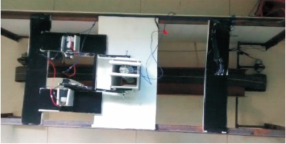
Figure 6. Capping Section of Project
The last section is, in which labelling has to be done on conveyer belt itself. After capping section the bottle will move forward, at the same time the labelled paper will get stick into the bottle while bottle is moving. In this way, the labelling to each and every bottle is done. This labelling bottle is done on running conveyor belt itself so it saves time. However, when the bottles get perfectly labelled and ready to sell, worker will manually place the bottle in box for selling.
The project of water bottle filling, capping and labelling is performed using ARM7 processor with LPC-2148IC. The project can be used for any liquid.
The process of bottle filling, capping and labelling is performed with very less time and without any major labor requirement. Labelling to bottle is done on running conveyor belt, so none of the time is wasted to stop conveyor belt for that task. Only one labor is needed to put the bottle and pick it after labelled. The time required as per the programming is fixed and no error is possible during the automation process. Timing required for one bottle of 500ml to get ready to sell is stated in Table 2.
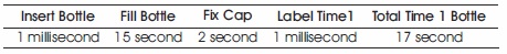
Table 2. Timing for One Bottle using Arm7
Compared to PLC the design using ARM7 controller is compact and less expensive. PLC took less time to fill bottle but capping and labelling process using ARM7 controller are superior and easier (Water Bottle, n.d.).
The process of filling the bottle using the 8051 controller is more time consuming. It took approximately 1minute to fill one bottle so the design using ARM7 controller is 2 times faster than 8051 controller.
The project of automatic water bottle filling, capping and labelling is done using ARM7 (Advance RISC machine) processor using LPC2148IC. It can also be done using different controllers. In moderate expenses and in less time with multitasking using arm processor project is successfully performed.
This paper states the comparison of performing same project using different controllers. It shows that the time required to complete the task is less for ARM7 controller. Also it does fill, cap and label without labor accurately. Considering the timing, speed, and accuracy, the overall performance of the program is best achieved using the ARM7 controller.
In future scope for the same project, if less number of sensor and DC motors are used the project budget will reduce and its perfection of work may remain the same. The project could be embedded within less space. Although it is a multitasking project, its speed should be high and total time taken for one bottle to get ready to sell can be decreased.