Figure 1. Block Diagram of System
The trends of electronic devices applications are changes with the evolutionary change in the electronics technology. The field of embedded technology is growing with advanced microcontrollers. Due to this, electronic system is widely used in different sectors for monitoring and controlling. On observation, it is found that controlling railway gate crossing is one of the most important concept and it is proposed to develop and deploy the advanced microcontroller for the same. Hence, the literature survey has been carried out and proposed to deploy advance microcontroller of PIC family to develop a prototype for the present system for monitoring and controlling the railway gate. For this the IR sensor is deployed to sense the position of the train and corresponding signal is processed by microcontroller according to the user firmware to generate control action of closing or opening the railway crossing gate. To cater the need of mechanical movement, DC motor is deployed in the proposed system. On investigation of the deployment of to prototype for practical purpose, it is observed that the system works successfully with high reliability.
The objective of the present research work is to design a smart embedded system to provide an automatic Railway Gate Controlling (RGC) at road crossing. Smart, here means, self decision making with high reliability and accuracy. Many times accidents are taking place, when the road users and railway users are simultaneously sharing the railway crossings. Many times the gateman is busy with personal work, due to this the road traffic is delayed or while closing the gate it becomes risky (Balamurugan et al., 2018; Anila et al., 2017). On observations of different sites in railway crossing, it is proposed to design a smart railway gate control system. Nowadays, the advance electronic system is widely used for different applications in industrial (Mane-Deshmukh et al., 2013), medical (Sharma et al., 2015), agricultural (Mane-Deshmukh, 2018b), environment and underwater parameter monitoring control. On extensive study of the smart electronic equipments, it is appropriate to use them precisely for monitoring and controlling different parameters.
The railway gate controlling through automation is one of the important concept that attracts the researcher to make development in this field (Arun et al., 2013; Punekarv & Raut, 2013; Swamy & Sivaprasad, 2017). It is found that, when the train is arriving at the railway crossing, the signal of the train is received at the gateman side through a traditional wired link. In the present system, once the train leaves the station, the station master informs the gatekeeper about the arrival of the train through telephone or wireless messages. Once the gatekeeper receives the information, he closes the gate depending on the time at which the train arrives. Hence, if the train is delayed due to certain reasons, then gate will be closed for a long time causing traffic block near the gates. Therefore, the road users may be dead locked. However, the gateman does not know the exact time and so he closes the gate earlier or when the train comes closer to the railway crossing; both of these are time consuming and risky too. To avoid such critical problems, it is proposed to design a smart automatic railway crossing control system.
Deploying the proposed system, gate should be closed automatically whenever the train arrives and the gate should be opened once the train leaves the level crossing (Leena et al., 2017). The arrival of train in both direction can be identified using sensors placed on either side of the track. Use of embedded technology makes this openloop control system efficient and reliable. For reliable sensing actuation mechanism, development of microcontroller based system is mostly recommended in which the microcontroller with promising features are available (Deshmukh et al., 2018). Availing the on chip resources of the microcontroller, the sensing, and actuation system of better reliability can be designed. This helps to enhance the knowledge of the software development. Due to attractive features of an embedded technology, researchers and students are showing their interest in undertaking the research work where as the facets of smart system design are ensured.
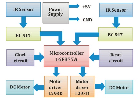
As shown in Figure 1, it is proposed to use two sensors to sense arrival and leave of the train. In fact, IR sensors are found to be more suitable for this application. Along with IR LED, the IR sensor comprises of IR Photo diode, whose output recognizes the presence of the train. One IR pair is used to detect the arrival of the train and another IR pair gives information regarding departure of the train. These two signals and digital signals can be read into the microcontroller through proper mean. Using these signals and co-developing the software, it is possible to ensure the atomization in the railway gate operation.
Figure 1. Block Diagram of System
To design the desired system the, smart embedded controller is required along with necessary peripheral devices for monitoring and controlling the railway crossing. More number of authors have designed and developed different systems for different applications, which are studied extensively and reviewed in this section.
Shrirao and Rojatkar (2016) have reviewed an automatic railway crossing control system. Microcontroller based automatic railway gate control system has been designed and reported by Pwint et al. (2014). The AVR microcontroller based automatic railway gate control system has been reported by Kottalil et al. (2014),where they deployed the IR-based sensors to detect the train position. Krishnamurthi et al. (2015) have designed AVRbased automatic railway gate control system. A smart railway gate control system is reported by sharma et al. (2015). In this study, the researchers have deployed RFID and pressure sensor to detect the exact location of train arrival and departure (Sharma et al., 2015). The microcontroller 8051 based automatic railway gate control system was designed and reported by Khulna and Bangladesh (2015). The Microcontroller 8052 based wireless automatic railway gate control system was reported by sanjiv et al. (2019). They have used ZigBee as a wireless communication device (Sanjiv et al., 2019).
The aim of the present research work is to develop a smart railway gate monitoring and control. This helps to reduce the accidents and increases the accuracy of railway gate control. For this, an embedded system is designed and reported in this manuscript. The o Figure 1. Block Diagram of System bjectives of the present system design are listed as follows,
The use of microcontrollers plays a commendable role in an automobile instrumentation. Therefore microcontrollerbased research work is undertaken and the present one is an embedded system, which consists of both hardware and software as the two sides of a coin, designed in our laboratory. The designing of hardware is described through the block diagram and description of the entire circuit. The block diagram of the system is shown in Figure 1. The system consists of various stages along with signal processing and microcontroller. In addition to this, power supply unit is wired as shown in the block diagram. According to the system block diagram, the smart electronic components are extensively studied and wired as shown in the circuit diagram.
As discussed earlier, the main aim of this research work is to design an automatic railway gate control system. On extensive study of the different required components for the present system design, the circuit diagram is designed and depicted as shown in Figure 2. On inspection of this Figure, it was found that, the hardware part of the embedded system is designed with microcontroller PIC 16F877A. This needs an embedded firmware, which is developed in Micro C Pro for PIC microcontroller and is programmed into target memory of the device with the virtual programmer. Both hardware and software are optimized for proper synchronization. After programming, the device is simulated and the operation of entire system has been studied and all bugs are removed, so that the system can be the design of an embedded system without any bugs. The circuit diagram is discussed through the following sections.
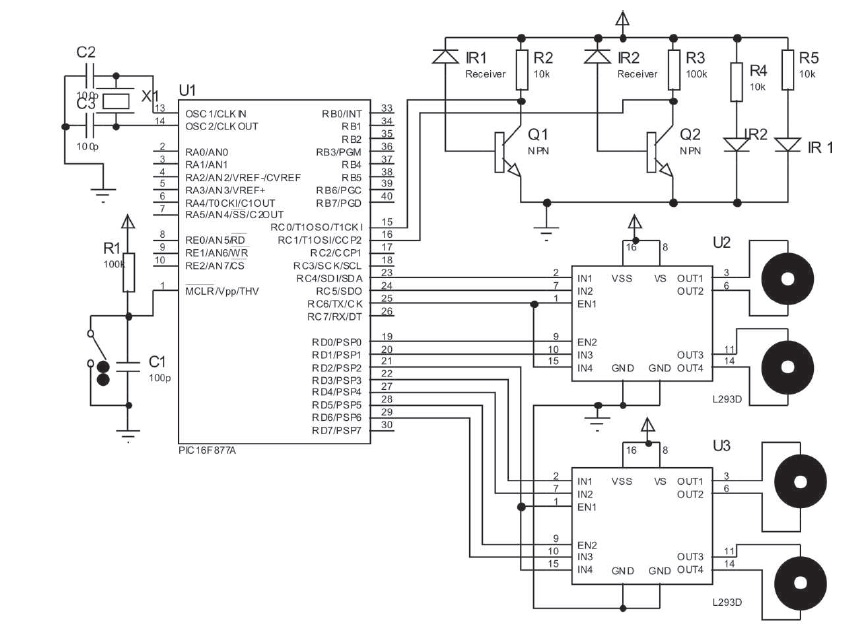
Figure 2. Circuit Diagram of System Under Investigation
To cater the need of present system design, the microcontroller is an important unit of the proposed system. The microcontroller helps to synchronize the operations of all interfaced peripherals. For this, the details regarding salient features of different microcontrollers are extensively studied and microcontroller from the PIC family is selected for the present design. There is a need for high speed and low clock frequency operated microcontroller, which is satisfied by the PIC microcontroller family. It has a wide range of microcontrollers with large variant. However, the 16F877A fulfills the needs of present embedded system, used in the present research work. The structural details of this microcontroller are studied and discussed.
The PIC core combines an instruction set with 32 general purpose working registers. All the 32 registers are directly connected to an Arithmetic Logic Unit (ALU), allowing two independent registers to be accessed in one single instruction executed in one clock cycle. The resulting architecture has more code efficient while achieving through puts upto ten times faster than conventional CISC microcontrollers. The PIC 16F877A provides different salient features (Adat et al., 2019). It has 16 K bytes of insystem programmable flash with Read-While-Write capabilities, 64 bytes of EEPROM and 64 byte of SRAM. The controller supports 32 general purpose I/O lines and 32 general purpose working registers. The I/O lines are sink and source upto 25 mA current. Hence, we can easily interface other devices to the PIC microcontroller. It has three flexible timers and counters with compare modes, and the timers are facilitated with pre-scale and postscale. Moreover, it has programmable UART, a byte oriented two-wire serial interface. In addition to this, PIC 16F877A supports a 8-channel ADC with 10 - bit accuracy.
Moreover, the Power-down mode saves the register contents, but freezes the oscillator, and disables all other chip functions until the next Interrupt or hardware reset. In Power-save mode, the asynchronous timer continues to run, allowing the user to maintain the timer base while rest of the device is sleeping.
In the present system, the microcontroller is used to scan the input, output lines and process the received signal according to the user’s, firmware. The user firmware is developed in the Micro C Pro and discussed in subsequent section of this manuscript.
In-System Programming is an essential part of the embedded system design. The advanced microcontrollers having on-chip flash programming memory of sufficient capacity. To program this memory, a typical programmer is required. Architecture and other features of the programmer depends on the architecture of the microcontroller and their flash memory. In this present system, we designed a simple In System Programming circuit using three resistors (Deshmuk et al., 2018).
As discussed earlier, the PIC 16F877A have 16 K flash program memory and demonstrates excellent features, such as In-Circuit Serial Programming. Therefore, instead of USB port, the deployment of COM port is recommended. Using these pins, the flash can be serially programmed. During this programming, two control signal, MCLR and Vcc, must be properly interfaced. By realizing the designing aspects, and employing COM port of the PC, the In-System-Programmer is designed for programming of the microcontroller and same presented in Figure 3.
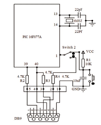
Figure 3. ISP of PIC 16F877A Microcontroller
As shown in Figure 3, only three 4.7k resistors are connected between DB9 connector and the PIC. This programmer operates at 5V DC. Deploying an Integrated Development Environment (IDE) PIC program, the hex file of firmware is flashed in the microcontroller. The developed firmware is discussed in the subsequent sections.
A distance meter commonly used as a obstacle detector, which consists of IR transmitter and receiver. Figure 4 depicts the IR transmitter and receiver. The signals transmitted by IR transmitter are received by receiver and supplied the input to the transistor. It is used to maintain logic levels of the IR output signal. Transistor BC-547 module used to maintain the input signal level in digital form. Its output is used in digital form as high and low logic without a change in the original signal form. The circuit schematic for IR transmitter and receiver module connected in the present research work is shown in Figure 5.
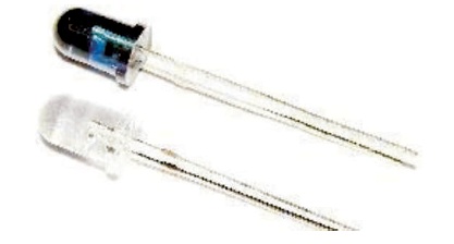
Figure 4. IR Transmitter and Receiver
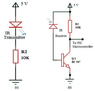
Figure 5. (a) IR Transmitter (b) IR Receiver Circuit Schematic of the IR Sensor
In this research work, IR transmitter transmits the IR waves on other hand these IR waves falls on receiver and it conduct to provide high pulse to the base of transistor. Due to this, the transistor turns ON and controller input pin is connected to the ground through the transistor. Hence, the controller receives logic level zero at the input when train is not present. When train comes, the IR rays do not falls on the receiver, hence at the base of transistor logic level zero is present. Due to this, transistor is OFF and the microcontroller receives a high logic level in the input. By receiving these signals, the microcontroller process the same and generates the control signal. The control signal is coupled to current driver and motor through the current driver. The control signal helps to open or close the railway gate for crossing.
The L293D is a high-current sourcing device designed to provide bidirectional drive currents upto 1 ampere, which is developed by Texas Instruments. It is operated at 4.5 V to 36 V (Mane Deshmukh, 2018a). It is designed to drive inductive loads such as relay switches, solenoids, DC and bipolar motors, stepper motors as well as other highcurrent/ high voltage loads in different applications. It realizes the TTL compatible design. Each output of L293D is a complete totem-pole drive circuit with a darlington transistor sink and a pseudo darlington source. The L293D have advanced features such high-noise-immunity, separate input logic supply etc. On extensive study of features of L293D, it is proposed to deploy the same in the present system design. It is wired as shown in the circuit diagram 2, the L293D is capable to drive two pairs of input. To enable each pair, it require to connect an enable input is high, hence the associated drivers are enabled, and their outputs are active and in phase with their inputs. When the enable input is low, those drivers are disabled, and their outputs are OFF and in the high-impedance state. However, for its practical application of the same, it require to replace the L293D by relay and the DC motor by AC motor.
We use DC motor for driving the devices. DC motor is run on direct current from a battery or DC power supply. When a battery or DC power supply is connected between a DC motor’s electrical leads, the motor converts electrical energy to mechanical work as the output shafts turns. We use high quality low cost motors as shown in Figure 6. This motor has a plastic gear box shell, which is connected to metal gears that ensures longer wear and tear. High quality gears are applied inside the gear box for providing the functionless rotation of gears. Other components, such as wheels, brushes etc. This motor can be operated with voltage range of +4V to +24V.
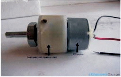
Figure 6. DC Motor Used in Present System
As discussed in the introduction, aim of the present system design is to develop an automatic railway gate control. The system must be reliable and highly accurate. However, any electronic system performance depends on the power supply applied in the system. If the power supply fails due to some problem, the system will stop. To cater the need of present system design, the solar panel is used as an alternate source with AC mains power supply as shown in Figure 7. In addition to that, the rechargeable battery of 12 V, 4 A is wired for use in critical conditions like in rainy seasons and when AC mains is OFF.
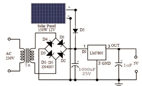
Figure 7. System Power Supply Circuit Diagram
We know that microcontroller is CMOS device, which consume very less power and needs +5V power supply. Moreover, other peripheral devices are operated on +5V and GND power supply. To produce power supply as per requirement, the three terminal voltage regulator IC 7805 is employed as shown in Figure 7. The power supply unit is built on the board itself.
In the embedded system, designing the development of firmware corresponding to the system is an important task. In present system the PIC family based PIC 16F877A microcontroller is deployed along with other necessary peripheral as discussed earlier. To synchronize the tasks of perpherals connected to the microcontroller, the firmware has been developed in Micro C Pro for the PIC Integrated Development Environment (IDE). It is facilated with rich library functions for different tasks, which supports to develop firmware in less time and errore free. For present system, firmware is developed for sesing the IR receiver input by the microntroller, if the input is 1, signal level is high for more than 3 minutes then it indicates the train is present and produces the signal to turn OFF the railway crossing gate. On other hand when input is 2, signal level is high for more than 3 minutes then it indicates the train is leaving the crossing and produces the signal to turn ON the railway crossing gate. Moreover, it detects the first signal indication of train from any side of the crossing and according to that control signals are produced. After creation of hex file, the firmware is flashed into the program memory of the microcontroller as discussed in in-circuit serial programming sub point. Figure 8 depicts the flowchart of the present system.
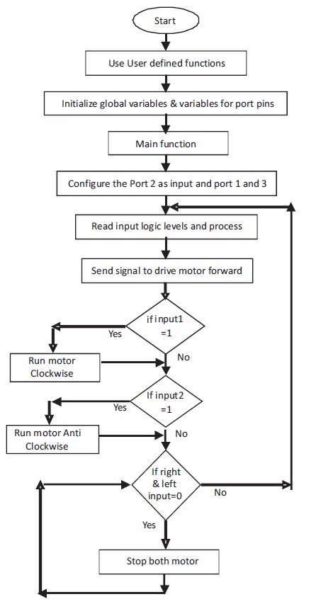
Figure 8. The Flowchart of the Present System
Major objective of the present research workwork is to demonstrate the concept of atomization in the railway gate control. To keep pace with objectives and recent trends in the embedded technology, the research work comprising hardware and firmware is completed. The IR sensors have been deployed to sense the position of the train, both of which arriving at the gate and departure from the gate. Moreover, to synchronise the tasks of peripheral devices, the embedded core PIC 16F877A is deployed in the present system, which works according to developed firmware. The firmware synchronously recognizes the states of the train and acts to open or close the gate of the railway crossing as discussed earlier in software. It is developed in embedded C environment and ported into the target memory of the core device. Entire research work is carried out in the our laboratory. The prototype of the research work is shown in Figure 9.
With the aim of demonstrating the operation of the present research work, the test bed consisting train route and toy train is developed and deployed for demonstration as shown in Figure 9, which depicts actual working of the project.
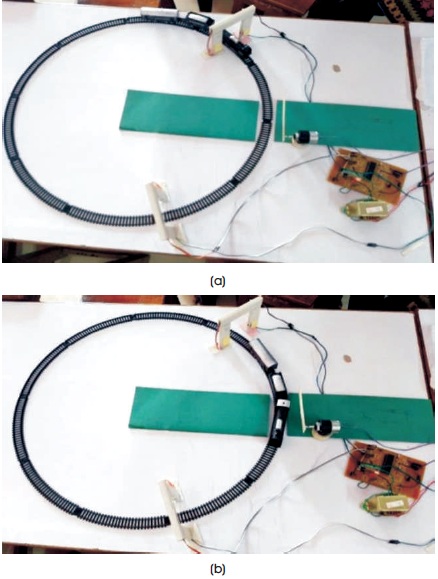
Figure 9. (a,b) The Prototype of the Present System
As shown in Figure 9, train is travelling on the dedicated route. The sensors are housed at typical places. The first location is well before crossing and send location is well after crossing. When train arrives at first location, the sensor senses the train location and produces continuous high pulse as output, which is input for the microcontroller. The controller process the signal according to the system firmware and produces the control action to start motor clockwise to close the railway crossing. Hence the motor rotates to close the gate. The gate remain closed till the train is detected by both location. When train departs from second location gate, the sensor senses and produces corresponding signal at the input of the microcontroller. According to user firmware explained in firmware section, the controller produces the control signal to activate the motor for opening the crossing gate, hence crossing gate gets opened to allow the road to be used.
As discussed earlier, the present research work demonstrates the smart automatic railway gate control system. But, to implement the same for practical purpose, it require to replace the L293D by using relay and the DC motor by AC motor. Whereas the firmware and other preripherals are remains same.
As per the objectives, the research work is completed. The research work depicts the accurate and reliable operation of the railway gate crossing monitoring and controlling. Moreover, it has been proposed to deploy GPS system to track the train for monitoring the location of trains.