Figure 1. Linkless type ECU
For fuel management of the engine and throttle valve opening, throttle position sensor plays the vital role. The traditional method for testing of such sensors at various angles and observe its effects was done manually. To overcome this method, the idea is to develop a system, which is fully digital and controlled automatically. The aim of the system is to provide controlling system, which includes sensing and identifying fault input signals from the throttle position sensor assembly. sensors. Also a system is implemented for calibrating an engine throttle position sensor operation of a system. This system not only improve the performance characteristics but also will be a time efficient system.
For fuel management of the engine and throttle valve opening, throttle position sensor plays the vital role (Conatser, Wagner, Ganta, & Walker, 2004). Each vehicle with an internal combustion engine has a throttle body, also referred to as a butterfly valve. This valve is positioned in the middle of the intake manifold and the air filter. The amount of air entering the engine is determined by the position of throttle. For fuel management, the component called throttle position sensor detects this position. The traditional method for testing of such sensors at various angle and observe its effects was done manually. To overcome this method, the idea is to develop a system which is fully digital and controlled automatically.
The throttle is a valve mechanism allowing to modify the amount of gas flow into the cylinders of a gasoline internal combustion engine. The dominant implementation of the throttle, in which the opening angle of the valve determines the amount of air inspired by the engine. The throttle is actuated directly by the driver through the gas pedal, and accordingly there was a mechanical connection between the two. The throttle position has to be sensed previously, in those systems in order to know the proper amount of fuel to be injected. The combustion process is heavily dependent on the appropriate air/fuel mixture, leading to the requirement of the throttle position sensor accuracy.
According to the literature survey, the proper precision and accuracy of throttle position sensor is needed as this is directly related to the fuel management. Different papers related to calibration of throttle position sensor have been studied. It is very important to calibrate the throttle position sensor to increase the accuracy as per the study (Koerner & Kenosha, 2006). For this, the research is done to convert the whole system to automatic and digital. Hence the accuracy of the system after the calibration will increase due to which ultimately the fuel efficiency will increase. This will be done in real time and hence the performance of the system will increase. This high precision calibrated sensor is then placed at the throttle body in the engine.
The detailed study of the literature review gives important outcomes such that how calibration of the sensor is important. They have shown two methods, which are able to quantify arbitrary displacements. The first approach leads to a general analytic solution. The second method was to reduce the computational effort, they derived a method, which is based on a linearized magnet model. Reddy, Murali, and Shaga, (2017) have presented a paper on a low cost scalable planar coil structure for measuring absolute angular position. The experimental results show that the coil structure exhibits linear response to position variation.
Conatser, Wagner, Ganta, and Walker, (2004) have presented a paper in which a real-time health monitoring strategy has been designed for an automotive electronic throttle control system.
Streib and Bischof (1996) have presented a paper which describes the consequences of such an integration for the ECU hardware and software.
Starkweather, Sandy, and McKenna, (2001) have presented a paper in which a self-diagnostic method was introduced for controlling an AMT system for sensing and identifying faulty input signals like Throttle Demand Potentiometer, Throttle Pedal Safety Switch and Ride Through Detent Switch (THD, THPS, and RTDS) from the throttle position sensor assembly sensors.
A typical Electronic Throttle Unit consists of three important components: (a) an accelerator pedal module (b) a throttle valve, which can be opened and closed by a motor and (c) an engine control module (Yadav, Gaur, & Tripathi, 2015). Types of Electronic Throttle Control System are as follows:
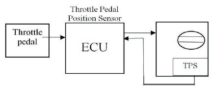
Figure 1 shows the linkless type of Engine Control Unit (ECU). The traditional system includes the mechanical element of a throttle cable, which is replaced by the fast responding electronics in the conventional system. Due to this, less adjustment and maintenance is required by the system (Streib & Bischof, 1996). The greater accuracy of data can improve the drive-ability of the vehicle.
Figure 1. Linkless type ECU
When we press the foot against the pedal, the sensors will measure how far is the foot pedal from its original position. This information is then send to the engine management system. The throttle valve can open or close according to the instructions from the motor which is send by the engine management system. The correct position is known with the help of TPS which will communicate with the engine management system. The amount of air which flows into engine which is dependent on how much the pedal is pressed and is controlled by the throttle body (Conatser et al., 2004).
A throttle body can be defined as the intake system component in fuel-injected engines that the driver controls with the accelerator. The throttle body shown in Figure 2 includes a Throttle Position Sensor (TPS), which helps in reporting the angle of this valve to the Engine Control Unit (ECU), where the information is further used in various calculations.
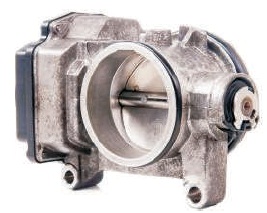
Figure 2. A typical Throttle Body
There are three types of throttle bodies:
The use of throttle body is to control the amount of air, which enters into an engine. The communication between the throttle position sensor and air flow sensor takes place with the help of computer. The ECU will manage the throttle and allow it to take in the amount of air that is needed by the engine.
Throttle position sensors, also known as TPS, are designed to sense and control the throttle position of a vehicle (Starkweather, Sandy, & McKenna, 2001). The engine control unit will manage the throttle and allow it to take in whatever amount of air is needed in the engine. There are 3 types of Throttle Position Sensor.
Potentiometric TPS shown in Figure 3 is widely used due to cheap prices for measuring rotational position. There is also other way of measuring a rotational position in a contactless way by using an inductive principle. Halleffect based magnetic sensors are used for this purpose. Following is the comparison of the types of TPS (Young, 1989).
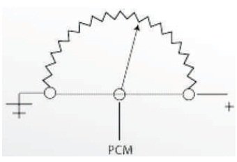
Figure 3. A Typical Potentiometric TPS
Table 1 indicates that cost wise potentiometric TPS is the best whereas magnetic TPS is less prone to noise and size is also less compared to others. Hence, it can be concluded that magnetic TPS is the best option to choose.
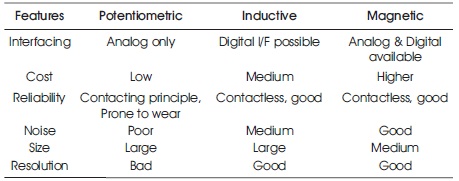
Table 1. Comparison of the Types of TPS
Before the introduction of drive-by-wire throttle bodies, Vehicles used wiper-style variable resistors to measure throttle position. These OEM sensors and the many re- branded low-quality sensors that look like them are prone to premature wear and unsteady measurements due to engine vibrations.
Contactless design is used by the hall effect sensor shown in Figure 4, which is highly resistant to vibrations, that is it has long life durability and will provide the reliable readings. In addition, the voltage output is extremely smooth and consistent since the Hall-Effect TPS is equipped with signal processor. This improved the engine responsiveness, idle condition, and improved throttle response, especially on vehicles with stiffer than stock engine mounts (Starkweather et al., 2001).
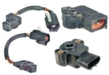
Figure 4. A Hall Effect TPS
The idea is to convert the manual calibrating system to fully digital and automated for the throttle position sensor. For this we use the microcontroller, renesas, which has industry based application. When the throttle position sensor is placed on the shaft, the motor will rotate the sensor. The position at which the motor is rotating can be sensed by the encoder (How to Mechatronics). In total the motor will rotate till the throttle position sensor rotates at 90 degrees (Reddy et al., 2017). After that it will come to the reference point. At the same moment the Wi-Fi will send the data to database for the continuous verification. The current status of the system can be observed on the LCD. Also we can interrupt the system or can give the inputs to the system using switches.
Figure 5 shows the block diagram of proposed system. To drive the throttle position sensor stepper motor is used. For sensing the position of the stepper motor incremental encoder is used. To communicate the system Wi-Fi module is used. To display the current status LCD is used. The working of the system is mentioned in previous sections. For programming purpose of renesas microcontroller, cube suite (CS++) named software is used.
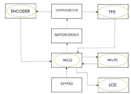
Figure 5. Block Diagram
Figure 6 shows that when the input is given to the controller through the keypad to the particular direction, the stepper motor moves in that direction and the degrees of the motor movement is displayed on the LCD display.
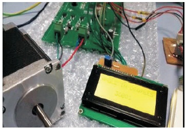
Figure 6. Angular Movement of Stepper Motor Displayed on the LCD Display
Figure 7 is the test bench for throttle position sensor testing and calibration (Stockbridge, Reason, & Steele, 2017). Incremental encoder will sense the position of the motor and will display on the LCD.
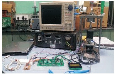
Figure 7. Test bench for Throttle Position Sensor Testing and Calibration
The required voltage is provided by the customer for the particular angles. The accuracy is of 95% compared to the required output voltage. Time required to test 1 calibrated sensor is about 5 minutes.
Table 2 shows the readings of the Digital system for testing of calibrated sensor of one sample of TPS.
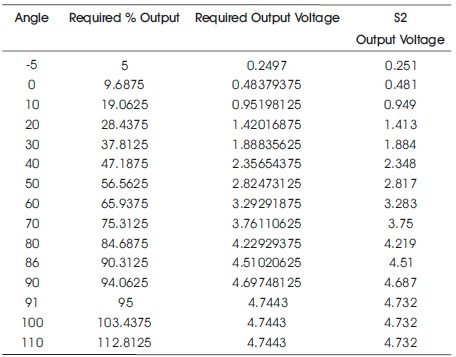
Table 2. Digital System Reading
Graph is plotted at the angle from 0 to 110 degrees considering the wide throttle open condition as per the range of throttle in the x-axis. On the y-axis obtained output voltage is plotted as shown in Figure 8.
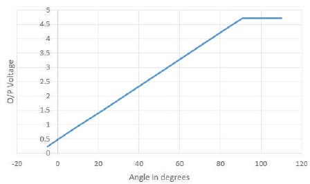
Figure 8. TPS Output Characteristics for Digital System
It is observed, the above graph is absolute linear in nature. This implies that the sensor is well calibrated.
In this paper, the traditional and the conventional methods for controlling the throttling with the help of electronic throttle unit are mentioned. The study concluded that linkless type of electronic throttle unit is the best option for the throttling. Type of throttle body to be used is decided on the basis of the weight of the vehicles. Contactless throttle position sensors are the trending type of TPS, which is Hall effect type. It has long life and has ability to work in high temperature.