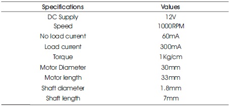
Table 1. Specifications of the Motors used
Underwater robots are used in surveillance, academic and military applications because of their capability to execute risky tasks underwater without human intervention. In this work, a robot is built at a low cost to carry out inspection at specified depth in a water body, controlled using IoT (Internet of Things) based technology. The main drawback with the currently developed Unmanned Underwater Vehicle's (UUV) are that they are controlled using cables, which is a problem for underwater surveillance due to their additional weight and possible harm with the water animals. But with the help of this work, IoT technology can be used to control the robot wirelessly under deep waters which increases the credibility of this work. With the use of Raspberry-Pi 3 Model B+ the robot can be connected to a smartphone or a laptop and will be controlled with ease. The Raspberry-Pi 3 Model B+ can be programmed using python programming language and different instructions can be given to the UUV. In this work, DC motors are interfaced with Raspberry-Pi. These motors are controlled using a smartphone or a laptop and depending upon the instruction given, these motors operate. A Raspberry-Pi camera module is placed at the front which is interfaced directly with Raspberry-Pi and is programmed for getting live video streaming. Focus lights are also placed for attaining better quality of video under the water.
Remotely operated vehicle is the common accepted name for tethered underwater robots in the offshore industry. Different from Autonomous Underwater Vehicle (AUV) (Pyo & Yu, 2016; Feezor, Blankinship, Bellingham, & Sorrell, 1997) Remotely Operated Vehicle (ROV) (Ghilezan & Hnatiuc, 2017) are tele-operated robots, highly maneuverable and operated from a command centre. They are linked to command centre by a tether which is a group of cables that carry electrical power, video and data signals back and forth between the operator and vehicle. Most ROVs are equipped with at least a video camera and lights. Additional equipments are commonly added to the vehicle to expand its capabilities. ROVs (Alekseev, Akinshina, & Kostenko, 1998; Christ & Wernli, 2014) can be used in a wide range of complex missions similar to AUV applications. ROVs are primarily deployed for underwater salvage, inspections, installations, and repair tasks and can also be used for naval, scientific and educational purposes such as; mine neutralization, marine ecology inspections, iceberg profiling, oceanographic sampling, and underwater photography.
Presently for underwater visual inspection expert divers are assigned to get into deep waters for checking ship debris, underwater ecological studies and different military purposes. But there are too many hazards for a human diver to get into water as there is a danger of water animals, water pressure, etc., in deep waters. In recent times there has been significant development of different Unmanned Underwater Vehicles (UUV) (Manjunatha, Selvakumar, Godeswar, & Manimaran, 2018), which are in action, but the main drawback with these UUV's are that they are wired, which is a problem for underwater surveillance.
To nullify the above problem, which is being faced in the UUV’s, this work is done. In this work, with the help of Raspberry-Pi 3 model B+, the robot will be connected to one of the device (smartphone/laptop) through, which it will be controlled. Necessary commands will be given to the robot using the same device. This will result in wireless control of the robot, increasing the credibility of this work.
The robot has 4 motors (Song & Arshad, 2016) for moving in all six directions. These are powered by a 12V battery and are connected to the Raspberry-Pi 3 Model B+ through a L293D motor driver circuit. As per the given instructions by the user using a smartphone or laptop these operate as per the logic of the program. Specifications of Raspberry- Pi 3 model and L293D motor driver circuit is given in Appendix 1-4 and in Tables 1 and 2.
Table 1. Specifications of the Motors used
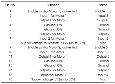
Table 2. Pin Description of L293D Motor Drivers
A Raspberry-Pi camera module is placed at the front part of the robot for live video streaming. This camera module is used for streaming live visuals using a proper program. The live visuals can be accessed by opening the IP address of the Raspberry-Pi 3 Model B+ in any of the devices which are connected to the same network. Two focus lights are placed on either side of the robot which help in streaming clear visuals of the underwater surroundings. A switch is provided for overall powering of the robot, simultaneously a terminal is provided for recharging the battery. Thus using this robot, one can execute many tough operations inside the water where human intervention is harmful and not possible. This robot is cable-free, which is an added advantage to the previous models.
There have been a number of studies in the field of underwater robotics and different researchers came out with different solutions for numerous problems that the underwater robotics possess. Many of them showed how an efficient ROV (Remotely Operated Vehicle) or an UUV (Unmanned Underwater Vehicle) or an AUV (Autonomous Underwater Vehicle) all nearly meaning the same can be designed and put into action in the real world.
Rubin (2013) has presented the recent advancement in compact designs in the field of underwater robotics. The study mainly focussed on Mini-ROVs, which has number of advantages and features that resulted in various applications. Some of the features are: Low Cost, Ease of Deployment and Use, Advanced Capability, Very Adaptable and Flexible, Durable and Reliable, Wide Range and Highly Capable, Size Appropriate Sensors and Minimal Training Requirements. On the basis of these features he developed this work (Rubin 2013).
Manjunatha et al. (2018) have developed a model of an underwater robot having a gripper for the visual inspection of external surface of pipes inside the water. In this study, low cost materials were used to develop a low cost system. Camera, gripper, and thrusters were placed for better working of the system. Wired technology is used to control the system in a better way.
Ghilezan and Hnatiuc (2017) have focussed on the communication and control of the ROV. Although their field of study was not about underwater vehicles but they discussed the upcoming controlling technology using IoT. Arduino-Mega was used as the main controller and different sensors and modules were interfaced to it. GPS module; an integral part of this work with which the exact location of the vehicle can be tracked. This study is very much similar to our study, the only difference is the controller.
Song and Yu (2016) have developed an Underwater Marking AUV, realizing the hard mission for human divers or robotic systems to investigate complex underwater environments, composed of several turning points and rooms. The paper explained a design of the Autonomous Underwater Vehicle (AUV) for marking physical and visible path logs in water. Then, it will make the repeated exploration easier. For the solution of underwater marking, they chose to use paraffin wax which can be melted easily in the heated body of machine and also be hardened easily in water. The vehicle has a container for storing the bulk of paraffin wax filament, nozzle part for ejecting the filament, and cameras for detecting filament mark. The marking method is similar with Fused Filament Fabrication (FFF) method of 3D printers. Nozzle motors extrude filament into nozzle, heating core melts it, and it comes out from the nozzle in water. As well as leaving a path mark, the AUV has the ability to find interesting places with realtime topic modeling algorithm and can draw a circle-shaped mark that can be detected the next time easily.
As shown in Figure 1 and Figure 2, the main component of the robot is the Raspberry-Pi 3 Model B+. This is connected to the smartphone and similarly other two laptops are connected to the same network. An app named “VNC Viewer” is downloaded in the smartphone and one of the laptops from which this Raspberry-Pi will be controlled. Corresponding python code will be written in “PYTHON IDLE”. The robot will be controlled by a smartphone and one of the laptops. The other laptop will be used for streaming live video. The program logic for these motors is mentioned in section 3.1 (full code is attached in the Appendix). This code is run and commands are given as per the logic of the program and the robot is controlled wirelessly.
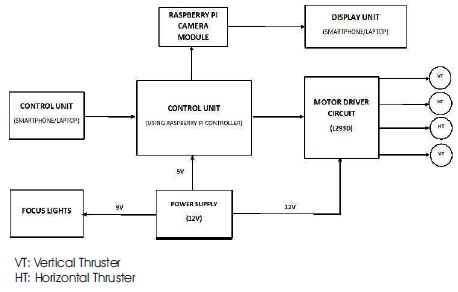
Figure 1. Block Diagram
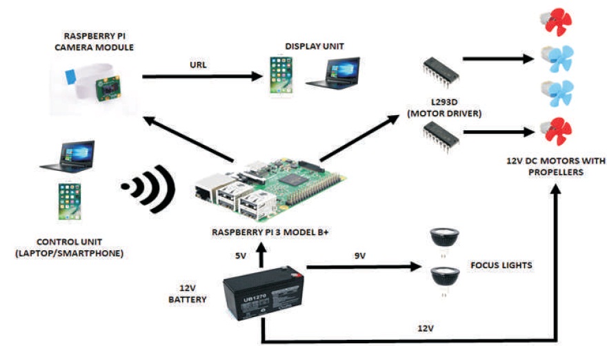
Figure 2. Graphical Abstract
3.1.1 Assigning GPIO pins of the Raspberry Pi 3 Model B+ to the 4 motors
As mentioned in Table 3, there are 7 inputs that a user can provide to the robot i.e., from 1 to 7. For each input there is a particular action that is performed by the robot as given in Table 3. If the input given by the user is not as mentioned in the above table, the robot will continue to perform the previously given input from the user.
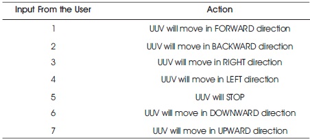
Table 3. Action for the Corresponding Input from the User
Figure 3 is the basic flow chart of the controls of the robot. Depending upon the inputs given by the user, the actions are executed by the system. The detailed execution and corresponding actions of each thruster is given in the below section.
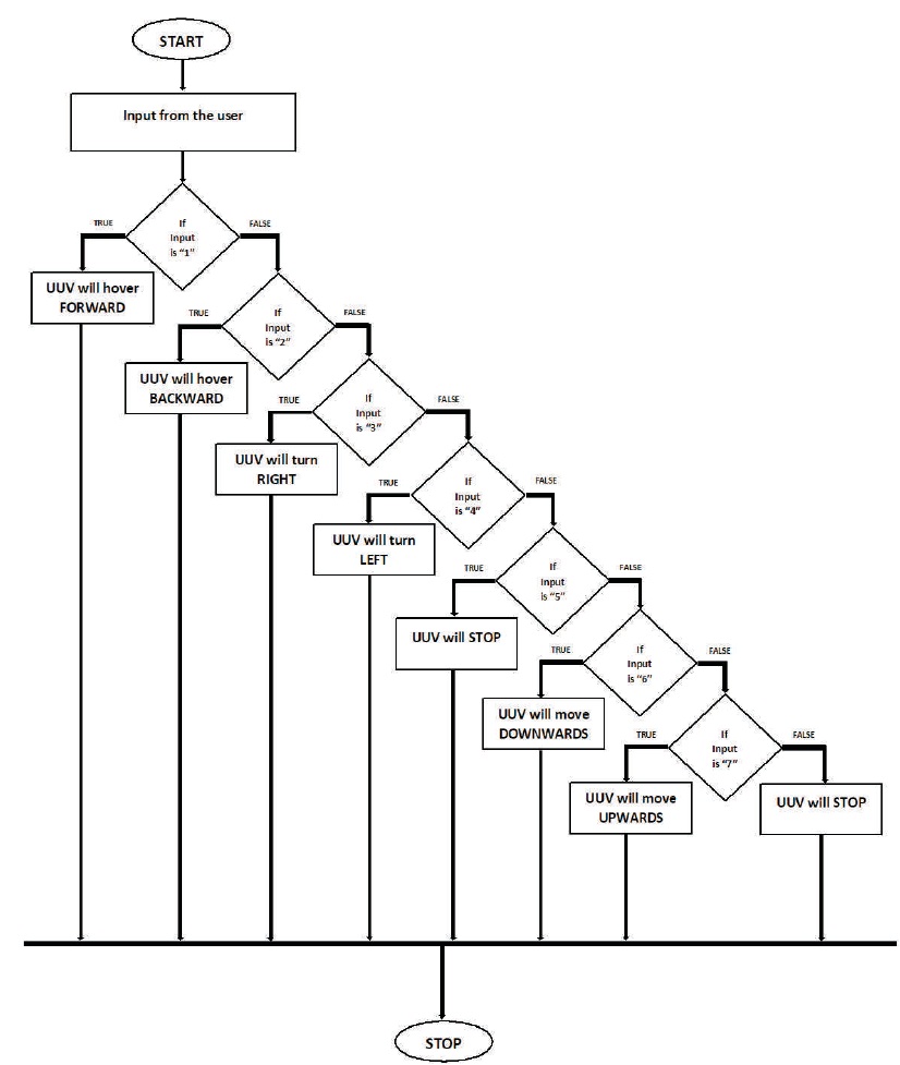
Figure 3. Flow Chart
3.1.2 Else-If Loop Execution
Horizontal Thruster(Left) – Clockwise Direction
Horizontal Thruster(Right) – Clockwise Direction
Vertical Thruster(Upper) – No movement
Vertical Thruster(Lower) – No movement
Horizontal Thruster(Left) – Anti-Clockwise Direction
Horizontal Thruster(Right) – Anti-Clockwise Direction
Vertical Thruster(Upper) – No movement
Vertical Thruster(Lower) – No movement
Horizontal Thruster(Left) – Clockwise Direction
Horizontal Thruster(Right) – No movement
Vertical Thruster(Upper) – No movement
Vertical Thruster(Lower) – No movement
Horizontal Thruster(Left) – No movement
Horizontal Thruster(Right) – Clockwise Direction
Vertical Thruster(Upper) – No movement
Vertical Thruster(Lower) – No movement
Horizontal Thruster(Left) – No movement
Horizontal Thruster(Right) – No movement
Vertical Thruster(Upper) – No movement
Vertical Thruster(Lower) – No movement
Horizontal Thruster(Left) – No movement
Horizontal Thruster(Right) – No movement
Vertical Thruster(Upper) – Clockwise Direction
Vertical Thruster(Lower) – Anti-Clockwise Direction
Horizontal Thruster(Left) – No movement
Horizontal Thruster(Right) – No movement
Vertical Thruster(Upper) – Anti-Clockwise Direction
Vertical Thruster(Lower) – Clockwise Direction
Similarly, another python code is written in “THONNY PYTHON IDE” for live video streaming from the Pi-Camera module which is placed at the front. Steps for enabling the camera and executing the code is as follows. The complete program is attached in the Appendix.
Raspberry-Pi Camera module used in this work can only be interfaced with Raspberry-Pi Models in which a separate slot is dedicated for the camera module. The camera can be used for different purposes such as capturing photos, video recording, and live video streaming. These operations can be done by python programming.
For obtaining live video streaming, the following steps should be followed.
Three PVC tubes of two different diameters are connected using 4 probes which form the main structure of the robot as shown in Figures 4, 5 and 6. A pi-camera module is placed at front of the robot covered by glass as shown in Figure 5. Focus lights have been attached to the smaller diameter PVC tube on the either side of the main PVC tube as shown in Figure 5. Terminal for battery charging and horizontal thrusters for the movement of the robot are placed as shown in Figure 4. Similarly two vertical thrusters are placed opposite to each other at the centre of the robot which can be seen in Figures 4, 5 and 6. A switch in also placed in the centre PVC pipe for overall switching of the robot as shown in Figure 6. The circuit board consisting of a Raspberry-Pi 3 Model B+, 2 motor drivers and a DC-DC Step-Down Buck Converter (for powering Raspberry-Pi) are fixed and are connected appropriately as shown in Figures 7 and 8. An inbuilt camera slot is available in Raspberry-pi as shown in Figure 8, where the camera is connected. The whole circuit board is fitted inside the main PVC tube and hence the robot is further sealed as shown in Figure 5.
The Figures 4, 5 and 6 depict the initial design of the robot which had a few flaws and failed during the first testing. But after certain necessary changes, the final design was obtained which is shown in Figure 9 and was tested successfully in the water up to 50m in length and 10m in depth without any problem as shown in Figure 10.
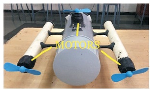
Figure 4. Rear View
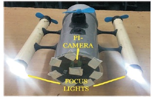
Figure 5. Front View
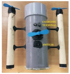
Figure 6. Top View
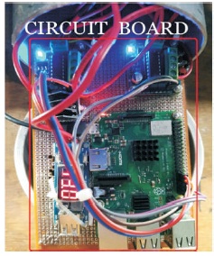
Figure 7. Circuit Board
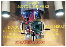
Figure 8. Circuit Board
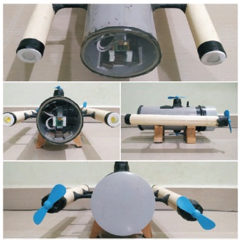
Figure 9. All views of the Final Design of the Robot
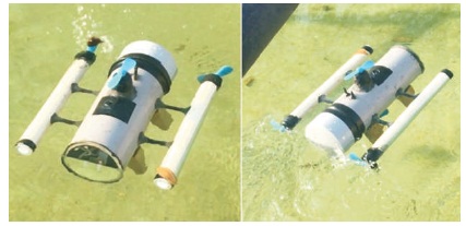
Figure 10. Real Time Testing of the Robot
An Underwater Robot has been built in this work which is wirelessly controlled by the user using Internet of Things technology. This piece of work mainly revolves around Raspberry-Pi 3 Model B+, which is the main component of the work. This main component i.e. the Raspberry-Pi, depicts a lot of advantages by having inbuilt wi-fi module, inbuilt slot for camera interfacing, etc., which are becoming an essential part of each and every upcoming studies in the field of IoT. Using this new model different applications such as defence operations, rescue operations, underwater oil and gas pipeline inspection, academic and research studies of underwater ecology, etc., can be easily carried out without human intervention into the water which can be dangerous at times. Irrespective of a few limitations such as less range of connectivity, less operational time and frequent charging of battery, this piece of work can be a great boon to the society because of its diverse applications. The main motto of this work being LOW COST, is properly justified as this robot is developed for less than 10,000 INR. Also this is made from components which are easily available in the market. Having a very compact design structure (32 x 28 centimetres), this robot can easily dive into the water, nullifying the effect of buoyancy.
Thus this work successfully helps in mitigating different consequences experienced in previous works such as wired/cabled control, limited operational area, etc.
In this work there can be some improvements which can be implemented further for better execution. The heavy battery used in this work can be replaced by lighter and more efficient battery (Li-Ion Batteries), which in turn will increase the overall efficiency of the robot. BLDC motors, which are waterproof and have a capability of speed controlling can be used instead of DC motors which are used in this work. With the usage Image Processing technique, the robot can be upgraded to trace specific matter inside the water for different applications. Also an Android/IOS mobile application can be developed for controlling the robot more conveniently. The structure of the robot can be built using more durable material which will result in long lasting operation of the robot. Solar cells can be installed for recharging the battery when the robot is not in use.
Table 1 lists the specifications of the motors that are used in this work.
Table 2 describes each pin of the Motor Driver, L293D. The function of each of the 16 pins are given along with their corresponding names.
importRPi.GPIO as GPIO
from time import sleep
import sys
#assign GPIO pins for motor
motor_channel = (29,31,33,35,36,38,37,40)
GPIO.setwarnings(False)
GPIO.setmode(GPIO.BOARD)
#for defining more than 1 GPIO channel as input/output use
GPIO.setup(motor_channel, GPIO.OUT)
while True:
motor_direction = input('Select Robot Direction- 1=Forward,2=Backward,3=Right,4=Left,5=Stop,6=Up ward,7=Downward')
if(motor_direction == '1'):
print('UUV moving FORWARD\n')
GPIO.output(motor_channel, (GPIO.HIGH,GPIO.LOW, GPIO.HIGH,GPIO.LOW,GPIO.LOW,GPIO.LOW,GPIO.LOW,GP IO.LOW))
elif(motor_direction == '2'):
print('UUV moving BACKWARD\n')
GPIO.output(motor_channel, (GPIO.LOW,GPIO.HIGH, GPIO.LOW,GPIO.HIGH,GPIO.LOW,GPIO.LOW,GPIO.LOW,GP IO.LOW))
elif(motor_direction == '3'):
print('UUV turning RIGHT\n')
GPIO.output(motor_channel, (GPIO.HIGH,GPIO.LOW, GPIO.LOW,GPIO.LOW,GPIO.LOW,GPIO.LOW,GPIO.LOW,GPI O.LOW))
elif(motor_direction == '4'):
print('UUV turning LEFT\n')
GPIO.output(motor_channel, (GPIO.LOW,GPIO.LOW, GPIO.HIGH,GPIO.LOW,GPIO.LOW,GPIO.LOW,GPIO.LOW,GP IO.LOW))
elif(motor_direction == '5'):
print('UUV STOPPED\n')
GPIO.output(motor_channel, (GPIO.LOW,GPIO.LOW, GPIO.LOW,GPIO.LOW,GPIO.LOW,GPIO.LOW,GPIO.LOW,GPI O.LOW))
elif(motor_direction == '6'):
print('UUV moving DOWNWARDS\n')
GPIO.output(motor_channel,
(GPIO.LOW,GPIO.LOW, GPIO.LOW,GPIO.LOW,GPIO.HIGH,GPIO.LOW,GPIO.LOW,GP IO.HIGH,))
elif(motor_direction == '7'):
print('UUV going UPWARDS\n')
GPIO.output(motor_channel, (GPIO.LOW,GPIO.LOW, GPIO.LOW,GPIO.LOW,GPIO.LOW,GPIO.HIGH,GPIO.HIGH,G PIO.LOW))
GPIO.output(motor_channel, (GPIO.LOW,GPIO.LOW, GPIO.LOW,GPIO.LOW,GPIO.LOW,GPIO.LOW,GPIO.LOW,GPI O.LOW))
#underwater robot -- live footage
#source code from the official PiCamera package
importio
importpicamera
import logging
importsocketserver
from threading import Condition
from http import server
"""\
"""
classStreamingOutput(object):
def __init__(self):
self.frame = None
self.buffer = io.BytesIO() s
elf.condition = Condition()
def write(self, buf):
ifbuf.startswith(b'\xff\xd8'):
# New frame, copy the existing buffer's content and notify all
# clients it's available
self.buffer.truncate()
withself.condition:
self.frame = self.buffer.getvalue()
self.condition.notify_all()
self.buffer.seek(0)
returnself.buffer.write(buf)
classStreamingHandler(server.BaseHTTPRequestHandler):
defdo_GET(self):
ifself.path == '/':
self.send_response(301)
self.send_header('Location', '/index.html')
self.end_headers()
elifself.path == '/index.html':
content = PAGE.encode('utf-8')
self.send_response(200)
self.send_header('Content-Type', 'text/html')
self.send_header('Content-Length', len(content))
self.end_headers()
self.wfile.write(content) elifself.path == '/stream.mjpg':
self.send_response(200)
self.send_header('Age', 0)
self.send_header('Cache-Control', 'no-cache, private')
self.send_header('Pragma', 'no-cache')
self.send_header('Content-Type', 'multipart/x-mixedreplace; boundary=FRAME')
self.end_headers()
try:
while True:
withoutput.condition:
output.condition.wait()
frame = output.frame
self.wfile.write(b'--FRAME\r\n')
self.send_header('Content-Type', 'image/jpeg')
self.send_header('Content-Length', len(frame))
self.end_headers()
self.wfile.write(frame)
self.wfile.write(b'\r\n')
except Exception as e:
logging.warning( 'Removed streaming client %s: %s',
self.client_address, str(e))
else:
self.send_error(404)
self.end_headers()
classStreamingSer ver(socketser ver.ThreadingMixIn, server.HTTPServer):
allow_reuse_address = True
daemon_threads = True
with picamera. PiCamera (resolution = '1080x840', framerate=24) as camera:
output = StreamingOutput()
#Uncomment the next line to change your Pi's Camera rotation (in degrees)
#camera.rotation = 90 camera.start_recording(output, format='mjpeg')
try:
address = ('', 8000)
server = StreamingServer(address, StreamingHandler)
server.serve_forever()
finally:
camera.stop_recording()