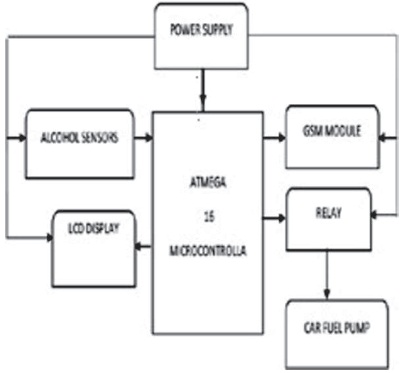
Figure 1. The System Block Diagram
It takes being alive and healthy to tackle challenges for sustainable development as well as harness the benefits thereof. The scourge of drink driving has led to loss of life and properties. Control measures to ensure drivers are not under the influence of alcohol while driving such as Blood Alcohol Content (BAC) check remains unrealizable due to the huge personnel, equipment, and maintenance cost involved. A less consuming effort has been proposed using MQ3 gas sensor mounted on the steering wheel, powered by the ignition of the vehicle, to detect alcohol level of the subject controlling it. The alcohol detected from the subject is processed by an ATMEGA 16 Microcontroller that compares it with a set threshold for compliance. If the threshold is exceeded, three modules are simultaneously triggered. The fuel supply control module is activated by a relay to cutoff supply towards bringing the vehicle to a momentary halt. The Liquid Crystal Display (LCD) module is activated to show alcohol has been detected. The Global System for Mobile communication (GSM) module sends the same notice on the LCD to subject's next-of-kin/law- enforcement-agent phone line for immediate attention. This system was developed and tested using a toy car. The result showed that it could be implemented in real life situation provided that all specifications are taken into consideration.
Vehicle transportation is the most patronized means of transportation in commuting people and products from one location to another. It is therefore expected to witness more road carnages than any other means of transportation, such as rail, sea, and air transport.
Drink driving is one of the major causes of road accidents all over the world, according to the Bureau of Transportation Statistics, every 2 hours three people are killed in alcohol-related highway crash (Chambers, Liu, & Moore, 2013). A major method for testing level of alcohol is the Blood Alcohol Content (BAC) test using breath-alyzers at check points. A 0.05% blood alcohol is enough to impair the sense of judgment when driving (Kousikan & Sundaraj, 2014). This method lacks credibility due to unavailability of required manpower, compromise on the part of inspection officers and the cost of maintaining check points over a wide geographical location.
This paper presents a better approach by developing a ubiquitous system that prevents drink driving on our roads thereby promoting safer roads and fuller lives.
In 1953, drink driving was detected using the Alco test developed by a German scientist Drager. It used variation in chemical coloration to check the concentration of alcohol in the subject's breath when exhaled into a tube containing the chemical (History of Drugs and Alcohol Testing, n.d). More recent is the vehicle safety system with automatic alcohol detector have been proposed to test Blood Alcohol Content (BAC) level in subjects driving a vehicle. But it was presented as a framework.
Navarro, Dino, Joson, Anacan, and Cruz (2016) have presented an Alcohol Detection System for Car Users using Iris Recognition Pattern. The proposed system comprised of a hardware and software system, which focused on the implementation of an algorithm that uses the Gabor filter. These systems operate in three stages, the first stage is capturing of the driver's iris image. Secondly, the iris image is encoded under a configuration, which will be receptive to computation and calculation. Finally, an indicator hailing from the open wellspring distinguished framework will control the car/vehicle through the utilization of a microcontroller encoded into a format, which is responsive to calculation and computation.
In James, Aparna, and John (2014), a comprehensive method of solving drink driving was proposed. The system was designed in a way that an alcohol sensor will be embedded on the steering wheel of a car. Whenever there is a kick starting attempt, the sensor measures the content of the alcohol in subject's breath and automatically switches off the automobile if tested drunk. However, the system lacks the ability to control the range at which the alcohol sensor senses alcohol, making it difficult to determine if it was not from passengers or passerby.
Kousikan and Sundaraj (2014) used an Infrared (IR) sensor, which was mounted on the steering to do the subject breath analyses. Ethanol has more capacity to absorb infra-red rays, therefore, when the car is turned ON the system uses an IR source led-894 to direct infra-red through the sensor continuously. If the flow of infra-red ray is interrupted by absorption of alcohol vapour, a relay circuit is activated. This relay circuit has control over the fuel supply system and it cuts-off the fuel supply to the engine. This makes the car to come to halt slowly. This method will work quite efficiently, but has some limitations. Systems that adopt the IR technology are larger in size therefore it will be difficult to incorporate the system into a steering. Another factor worth putting into consideration is that it does not use programming which makes the IR sensor method more complex and limited in terms of functionality.
A method in Vaishnavi, Umadevi, Vinothini, Rao, and Pavithra (2014) presented something similar to James et al. (2014). The difference was the usage of the MQ2 gas sensor. This method for many reasons is questionable in the sense that the MQ2 sensor is used for the detection of combustible gases. Since the main target gas is ethanol, the use of the sensor will prove inefficient because not all combustible compounds contain alcohol.
Khan and Khan (2013) suggested the use of a single alcohol sensor chip to sense the breath of the driver continuously. However, their method lacks the ability to improve the victims' situation when the car comes to a halt.
A comprehensive method of tackling drink driving by Dai, Teng, Bai, Shen, and Xuan (2010) was achieved with mobile phone placed in a vehicle and with accelerometer and orientation sensor. A program installed on the mobile phone computes accelerations based on sensor readings, and compares them with typical drunk driving patterns extracted from real driving tests. Once any evidence of drunk driving is present, the mobile phone will automatically alert the subject or call safety/security personnel for help well before accident actually happens. This method in many ways might prove inefficient because it could be easily maneuvered or bypassed, if the phone switches OFF, the safety system goes OFF as well.
In this paper, an alcohol sensor (MQ3 gas sensor) that senses the surrounding environment at limited distance apart is used. This sensed information is fed to an ATMEGA 16 Microcontroller that processes the sensed data by comparison with a preset threshold value. If alcohol is detected the microcontroller outputs signal to the Liquid Crystal Display (LCD) Display and Global System for Mobile communication (GSM) module notifying the subject and other relevant bodies of the discovery. The microcontroller also outputs activation signal to a relay ensuring the vehicle is brought to a stationary position at the instant. A block diagram representation of this system of operation is shown in Figure 1.
Figure 1. The System Block Diagram
The system circuitry is displayed in Figure 2. The flowchart showing the mode of operation is as shown in Figure 3.
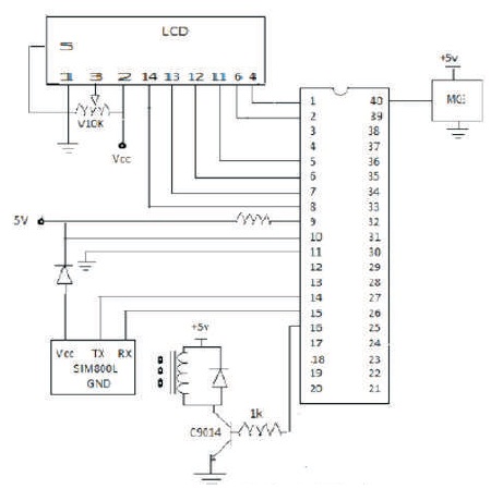
Figure 2. The Vehicle Safety System with Alcohol Detection Circuit Diagram
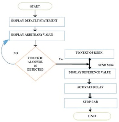
Figure 3. The Vehicle Safety with Alcohol Detection Flowchart
A simulation test was carried out using Proteus 8 (software). The result is shown in Figure 4. Table 1 is a list of component costs used to realize this work. This cost excludes damaged components, which were later replaced. It is expected that the errors made here will be avoided subsequently.
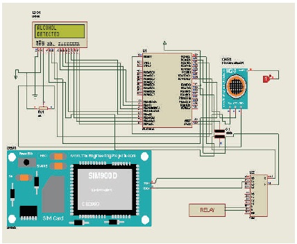
Figure 4. System Circuit Simulation on the Proteus Environment
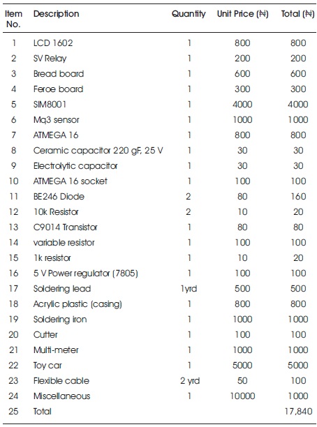
Table 1. Bill of Engineering Measurements and Estimation
This section presents the constructed circuitry, the on-board display of the devices used and the short message service (SMS) notification sent to a remote location using GSM technology. A multimeter was used to carry out continuity test on all components and to ensure device specification were strictly adhered to.
The power supplied to every unit was measured at each unit starting from the output pin of the voltage regulator and the corresponding results is recorded as seen in Table 2, such as the power supplied to the GSM module, the voltage input of the gas sensor, and the input and output voltage of the microcontroller. This was achieved with the aid of a multi-meter.
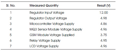
Table 2. Power Supply Test Result
The communication unit of this system comprises of GSM module and some components such as diode and the capacitor to ensure the SIM800l runs smoothly. The SIM 800l voltage requirement is quite lesser to the voltage requirement of all other components on the system, so the diode was used to reduce the voltage supply to the GSM module to 3.75 V. The SIM800l was observed not to function properly because it needed a smoother current for its operation. A 220 microfarad (μF) capacitor was used to achieve this. After making all adjustments, the GSM module was tested by exposing the gas sensor to alcohol and a message was received as expected.
The relay unit in this system completes or breaks the circuit. To test the efficiency of the relay, the vehicle safety system with alcohol detector was connected to a toy car and powered with a 12 V DC power supply. The car was noticed to move continuously when the acceleration button was pressed on the remote control. The motion of the car was also noticed to come to a standstill immediately when the system was exposed to alcohol, signifying that the relay has enforced a break in the circuit at approximately 5 V supplied at that instance.
The sensor unit was tested to make sure it works adequately; this was achieved by exposing the sensor to different concentration of alcohols after which readings of the change in voltage level were recorded as seen in Tables 3 and 4, respectively. Different alcohol concentration gives rise to different voltage level as seen in Table 4. The proportionality of the sensor voltage and alcohol concentration makes it easier to determine the percentage alcohol in a Driving Under Intoxication (DUI) victim's blood. However, the threshold has been set to 5 V required to activate the relay.
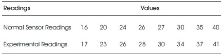
Table 3. Alcohol Sensor Readings
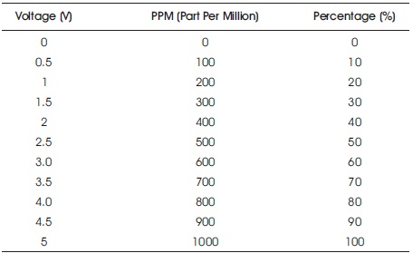
Table 4. Alcohol Sensor Sensitivity Level Characteristics
To verify the readiness of this unit, the system is powered after interfacing the LCD with ATMEGA 16 microcontroller.
It can be seen in Figure 5(a). Also, a variable resistor connected to pin 3 of the LCD is adjusted to adjust the LCD brightness (see Figure 2). Figure 5(b) gives a closer picture of the display showing a prompt that alcohol has been detected and an SMS notification has been sent to preregistered numbers.
Figure 5(c) shows the feroe board circuitry after ascertaining the system components are working as expected. Figure 5(d) shows the casting of the system into a transparent casing. The choice of casing was purely by intuition. Figure 5(e) shows the GSM notification message at the receiver (next-of-kin or law-enforcement-agent) end. Figure 5(f) shows the top view of the constructed system.
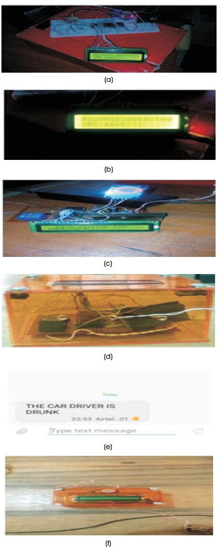
Figure 5. (a) Bread Board Circuitry (b) Output from LCD (c) Feroe Board Circuitry (d) System Casing (e) Mobile Phone Alert (f) Casing Top View
Problems encountered in the course of this work were noted for avoidance of similar experience. One of such was the problem of inductor spiking. This arose as a result of wrong connection of diode terminal in the relay unit. It led to the damage of the voltage regulator on several occasions. Another problem was the inability of Sim8001 GSM module to register local network. This was as a result of the minute pulsating input voltage. It was rectified using a 220-micro farad capacitor to filter the input voltage of the GSM module.
This work has been able to consider the limitations of other work to provide improvement in the control of driving under the influence of alcohol. The MQ3 sensor and ATMEGA 16 microcontroller used have brought novelty to this work. In addition to that, SMS notification prompting immediate attention has been in-cooperated to make the system more robust. However, there are still areas of improvements to be high-lighted.
The system proposed has been implemented using a toy car. The test showed that the Mq3 sensor has high sensitivity to alcohol compared to other types mentioned in literature. The microcontroller helps to automate the system thereby reducing overheads that would have been incurred from personnel and maintenance cost. The relay operating voltage (5 V) was the set threshold for alcohol detection. It is recommended that future work should consider tracking the subject driving under influence of alcohol via Global Position System (GPS). Motorcycles and bicycles can also be considered to have this system. A major problem in the implementation of this solution is the involvement of drivers.
A possible solution is for vehicle manufacturers to incorporate this technology to alert drivers on the state of drunkenness as observed in the use of seat belts.