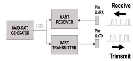
Figure 1. Module of UART
Universal Asynchronous Receiver Transmitter (UART) nowadays become more popular for serial communication over a computer or any other peripherals. UART is based on the serial communication protocol used for very short distance communication. It works on full duplex transmitter and receiver mode. UART is specially designed for the interfacing between RS232 line and Microcontroller so that any serial communicating device can easily connect with the other peripherals. It allows the exchange of the data between the processor and peripherals. The serial communications are assumed to have more reliable data transmission than the parallel communication. The parallel devices require more hardware due to which the circuitry becomes more complex as compared to the serial communication device. In this paper, verilog based UART has been proposed to design.
The UART converts parallel data into serial data due to which long distance communication takes place at low cost since the hardware requirement are less for serial communication device, whereas for parallel communication device, the hardware requirement is more, which will increase the complexity as well as the cost of the circuit (Fang & Chen, 2011). UART has numerous features in which we use very less in comparison to its full feature. It allows full duplex communication in serial link. It is a very common technique used for the data communication or transferring of data between the devices. So it has large application in the field of data communication and control system (Kedar, 2014). Only two signal lines are used for the basic communication through UART i.e., RXD, TXD. These two lines are capable of performing full duplex operation through any media connected with it. The binary signals were used to distinguish between transmitter and receiver lines. These binary bits are 0 and 1. Zero represents low state and 1 represents high state. Depending upon the status of the transmitter and receiver, the binary bit are set or reset that is either highest state or low state (Laddha & Thakare, 2013a). When the transmitter remains ideal then the data line will be at high logic state, whereas when the transmitter is ready to transmit, the data line will become low. To initialize this operation, “Start bit” is added to the beginning of the word to be transmitted. This start bit is only used to make the receiver active so that the data transmission can take place. During this operation, the clock used at both the ends should be synchronized in such a way that no data can be lost during communication (Rawat & Ramola, 2015). UART contains three major sections or components that are transmitter, receiver, and baud rate generator which is a frequency divider. Asynchronous indicates that it can recover character timing information from the data stream on the basis start and stop bits provided in the starting and ending of the data stream (Yuan et al., 2010). The UART is used to Interface between slow and fast devices so that proper communication can take place. Due to these reasons, it is used for short distance communication at low cost. Once you start to sent bits, the initial operation starts from LSB to the MSB bit. The transmission time for each bit remains same so that each bit contains same time (Moussa et al., 2013).
In this communication, a number of data is to be sent at the same time either in the form of blocks or frames. Transmission speed of this communication is faster since more data is transmitted at same time. Due to this reason, it is more expensive. During the transmission of large data, the gap between the data is not present.
In this communication, either one byte or character is transmitted or received at a time. Due to this reason, the transmission speed is slow as compared to the synchronous transmission. Since single byte or character is transmitted at a time, it is less expensive and random in time interval, and the gap between the data is present in this communication.
VHSIC Hardware Description Language (VHDL) is a very high speed Integrated circuit based hardware description language, whereas verilog is the language of verifying logics. The language is very similar to the pascal language, which is an alternative language of VHDL to specify the RTL logic synthesis of the VHDL (Ansari & Farooqi, 2012). VHDL comes under rich typed language. Ada programming language is the main source from which the VHDL programming language is derived which are more verbose than the verilog. Since VHDL does not define availability, the strong typing requires additional coding to explicit VHDL, which does not define any simulation control or monitoring capabilities within the language. In comparison to the VHDL, verilog is weak as well as the language is of limited type. Verilog is derived from C programming language and an older HDL called Hilo. All the other data types used in verilog are predefined (Yu et al., 2007).
The main objective of this paper is to design an UART module so that a proper communication takes place between high speed peripheral devices and low speed peripheral devices.
From review of related work and released literature, it is observed that many researchers have designed UART by means of making use of specific techniques like algorithms, logical members of the family. The UART used for the serial communication protocol provides the entire duplex conversation in serial link. The design of the hardware implementation has a high speed and UART utilizing area Programmable Gate Array. The UART has three modules, i.e., receiver, transmitter, and baud rate generator which also works as a frequency divider. These modules are simulated on ModelSim SE 10.0a and designed through making use of Verilog description language, which has been synthesized on Field- Programmable Gate Array (FPGA) kits like as Spartan 3 and Virtex 4. On doing the comparative evaluation, there is a change in between the number of slices, LUTs, and the maximum frequency. The results are relatively good and steady and have high-quality flexibility with high integration. In making the UART if we use FIFO, the design becomes more stable, reliable, and more flexible, which supplies absolutely better bps rate (Longadge et al., 2015). A UART is a full duplex receiver and transmitter. It is the chip with inbuilt programming that offers controls on a computer's interface to its attached serial devices. It controls the transmission of serial and parallel knowledge. The whole mission of serial transmission is performing on the principle of the shift register. In knowledge transmission by means of the UART, once the baud rate has been generated, both the transmitter and the receiver's inside clock are set to the same frequency (Shrivastava & Sharma, 2014). Tenure is concerned, establishing a serial conversation protocol together with bit synchronization, frequency division according to the input clock. All modules are simulated on Xilinx ISE (Kumar & Angadi, 2012). This offers a design of an asynchronous FIFO and structure of the controller. This controller is designed with UART circuit block and FIFO circuit within FPGA to set up communication in modern complex control systems with comfort. This controller can be used to establish information exchange, when master equipment and slavery equipment are set on the separate baud rate. To lower synchronization error between subsystems in a approach with a few subsystems, we are also able to use it. The controller is scalable and reconfigurable. There is also large discipline difficulty (Laddha & Thakare, 2013b). This work proposes an integrated architecture for a UART module to be used with MIMO-OFDM hardware platform, the cause of this module is to enable the communication process between FPGA board and MATLAB. There is also design complexity (Moussa et al., 2013). There are various problems that exist with the previous methodology which are reduced in this method. To overcome the problem of routing and extra space requirement, UART IC is implemented on FPGA board. Regarding flexibility and cost, it has the ability to update its functionality by using partial reconfiguration of the portion in the design.
From the initial stage this design is divided into three stages. First, the design of baud rate generator. Second, the receiver end module, and third is the transmitter end module. Figure 1 shows the module of UART.
Figure 1. Module of UART
Initially, the baud rate generator helps in providing the clock (local clock), which is required to be higher than the requirements of the transmitter and the receiver modules. The RXD pin used to produce alert signals by the receiver module, which is being converted into parallel information. And similarly, the transmitter module sends the signal in terms of serial through RXD pin, which are being further converted and forwarded to the transmitter modules. The UART frame format is shown in Figure 2.
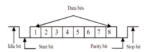
Figure 2. UART Frame Format
UART hardware operations are controlled by means of a clock signal which runs at a different data rate. For instance, every knowledge bit could also be as long as 16 clock pulses. On each clock pulse, the receiver tests the state of the incoming indicators, and looks for the beginning of the start bit. If the apparent start bit finishes at the least one-half of the bit time, then it is discovered to be valid signals to establish a new character (Patel et al., 2012). If not, then the duplicate pulse will be eliminated. After ready for the other bit time, the state of the line is again sampled and the resulting level clock becomes a shift register. After getting the specified quantity of bit intervals for the character length (5 to 8 bits, in general) eliminated, for the receiving approach, the contents of the shift register is made to be available parallely. The UART will set a flag, indicating new information to be available, and may also generate a processor interrupt to request that the host processor transfers the received data. On every alternate of data line, the satisfactory UARTs "resynchronize" more than a half bit. In this approach, when the transmitter is sending at a different speed than the receiver, they reliably receive (This is the normal case, on the grounds that apart from the communication signal, communicating units probably do not have any shared timing process). The receiver system is shown in Figure 3.
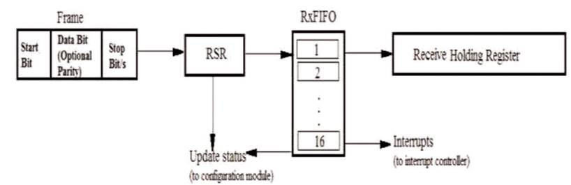
Figure 3. Receiver Subsystem
The Transmitter subsystem transmits the signal by placing all the data into the shift register and simultaneously the receiver starts receiving the signal. The UART produces signal along with the parity bit including start and stop bits. The transmitter subsystem is shown in figure 4.
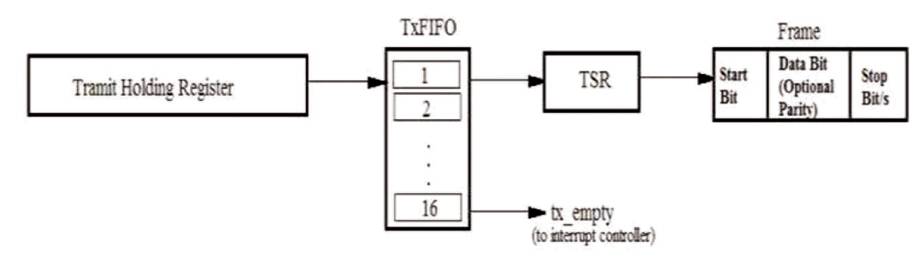
Figure 4. Transmitter Subsystem
Baud rate generator is a module which is used in the initial stage to specify the rate of transmission and reception of the signal. The transmitter transmits the signal and the receiver receives the signal at the same rate on which the rate is defined by the baud rate generator.
Divisor (decimal) = (clock frequency) / (baud rate x clock sampling rate)
In this paper, a verilog based UART design is proposed and implemented successfully. This design consists of three modules, i.e. Baud rate generator, Transmitter, and Receiver modules. All these three modules were implemented successfully using verilog or simulated by Xilinx ISE. This design helps in reducing the routing problems, issues related to cost, and also improves flexibility.
Expression of giving thanks are just a part of those feelings which are too large for words but shall remain as memories of wonderful people with whom we have got the pleasure of working during the completion of this work. We are grateful to Shri Shankaracharya Institute of Professional Management and Technology, Raipur which helped me to complete this work by giving encouraging environment. We would like to express my deep and sincere gratitude to my supervisor, Assistant Professor, Upendra Soni. His wide knowledge and his logical way of thinking have been of great value to me. His understanding, encouraging, and personal guidance have provided a good basis for the present work.