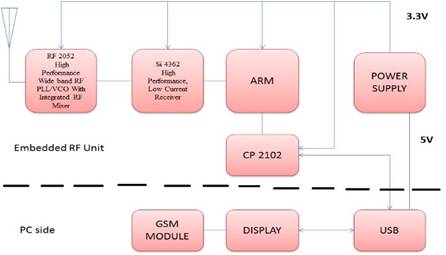
Figure 1. Block Diagram of Advanced Embedded Electromagnetic Radiation Monitoring System
The design and implementation of Advanced Embedded Electromagnetic Radiation Monitoring System (AEERMS) for the monitoring of the non-ionizing Electromagnetic radiation is presented in this paper. AEERMS monitors the exposure of electromagnetic radiations continuously that are radiated from different RF sources. As per the pressing need, there is a tremendous increase in the usage of cellular mobile communications and broadcasting systems, which in turn increases the number of cell towers. All the cell towers together, transmit several tens to hundreds of watts of power, and the continuous exposure to this Electromagnetic (EM) radiation results in severe health problems like Brain Tumor, Blood Brain Barrier, Eye& Hearing etc. A systematic and continuous monitoring of the EM radiation is necessary to regulate the radiation level. The proposed system called AEERMS has the provision for continuous monitoring and display of radiation levels in the mobile network based on their frequency range and stores and/or transfers the data to concerned authorities. The proposed AEERMS was successfully implemented in measuring the radiated power of the received signals with frequency ranges from 80 MHz to 2.5 GHz. In addition to this, system is also capable of scanning all possible frequencies in its vicinity and thus measures the total radiated power for all the signal frequencies. The performance of the AEERMS is validated with BSNL drive test. Tirupati at GSM frequency of 1800.6 MHz and at 3G frequency of 2156 MHz. The AEERMS is set in use under different traffic conditions, viz., normal and busy traffic conditions, at various distances from the cellular base station. It is observed from the measured radiations that, the radiation level in busy hours is larger than that in normal hours, irrespective of the distance from the cellular base station. The radiation levels are indicated by the particular frequency and radiation in terms of power levels. If the radiation level is above -30 dBm, then the monitoring system indicates it as a dangerous level of radiation, and it sends short messages to the concerned authorities indicating about the dangerous level of radiation of particular frequency in a particular place. The radiation levels are taken from BioInitiative (report) 2007 and 2012.
Cellular mobile communication was started to be widely utilized in the 21st century all over the world [7], [6], [18]. From the beginning, utilization of them has rapidly risen. Because of the augmenting number of mobile phone users, the numbers of base stations which enable mobile phones to connect to other mobile phones, are to be increased to provide a better communication. Therefore, base stations are to be mounted closer to each other.
With an increase in cellular mobile communication, number of cell towers getting installed is increasing every day. In India, currently there are nearly 5.5 lakh cell phone towers, and to meet the communication demand, the number will increase to 10 lakh towers by 2020 [5], [11], [3], [4], [9]. Majority of these towers were mounted near the residential and office buildings to provide good mobile phone coverage to the users. The base station tower and its transmitting power are designed in such a way that, it covers a distance at which the received signal strength is enough for proper communication. A building located near to the cell tower receive more strong signals than the building located farther from the cell tower. Continuously receiving these harmful signals causes serious health hazards to the people[8], [10]. In cities, urban and suburban areas like Chennai, Hyderabad, Vizag, tirupathi, Bangalore, Delhi, etc., millions of people reside within these high radiation zones.
The electromagnetic environment consists of natural radiation and man-made electromagnetic fields that are produced either intentionally or as by-products due to the use of electrical devices and systems. The natural electromagnetic environment originates from terrestrial and extraterrestrial sources such as electrical discharges in the earth's atmosphere and radiation from the sun and space. The everyday use of devices and systems emitting radio frequency (RF) electromagnetic fields is increasing continuously. Sources generating high levels of electromagnetic fields are typically found in medical applications and at certain workplaces. Medical devices used for magnetic resonance imaging, diathermy, hyperthermia, various kinds of RF ablation, surgery, and diagnoses may cause high levels of electromagnetic fields at the patient's position or locally inside the patient's body [13], [2], [15]. For broadcasting, high RF power is generally required to maximize the area of coverage. Close to the antennas, electric field strengths can reach several hundred volts per meter. Even higher values can be found close to occupational sources used for processing of various materials by heating and sometimes by formation of plasma discharge in the material. In many such applications, RF-safety problems arise because RF- power is high and it may be difficult to enclose the field-generating electrodes and processing space inside a good electromagnetic shield. Sources used by the general public, for example, wireless communication, data transmission or food processing generate comparably much lower fields at the position of the user. But this may also depend on the behavior of the user, especially concerning the distance to the source.
The proposed system is used to monitor EM radiation of the different RF sources. It consists of printed elliptical planar monopole patch antenna, [14], [17], ARM controller, [16] and [12] Module. All these compoments are integrated into a single system block diagram representation as shown in Figure 1.
Figure 1. Block Diagram of Advanced Embedded Electromagnetic Radiation Monitoring System
The printed elliptical planar monopole patch antenna receives signals of frequencies ranging from 80 MHz to 2.8 GHz. Initially, the antenna is virtually simulated in the Computer Simulation Technology (CST) studio and analysis of the antenna performance is carried out by computing the parameters like return loss, VSWR, impedance, radiation pattern etc. When satisfied with the simulation results, the antenna is practically fabricated on a square shaped substrate RT Rogers (5880) material. The fabricated antenna with VSWR < 1.3 is capable of receiving the signals in the frequency range of 1700 MHz and 2.4 GHz. The parameters of the fabricated antenna are practically verified at DLRL, Hyderabad [19] .
The experimental setup consists of fabricated antenna (Printed Elliptical Planar Monopole Patch Antenna), RF2052 manufactured by RF micro devices, Si4362 designed by Silicon Labs, NXP semiconductors manufactured ARM 32-bit (LPC2148) Controller [1], CP2102 data transfer module designed by silicon labs [16], [17], [12], [RMD] a general purpose Persona Computer (PC) is used as display section, and a GSM module as a data dongle. The general purpose PC loaded with visual Basic 2010 and CDEEC-RF PC Client (visual basic 2010) is used for both the graphical interpretation of the data and the interfacing between the user and the monitoring system.
The signal received by the antenna is fed to [14] which has a wideband RF PLL/VCO with integrated RF mixer. Then the signal is brought to [17] which is having RSSI (Received Signal Strength Indicator) which estimates the signal strength in the channel to which the receiver is tuned. The signal is then given to ARM controller via CP 2102 which is a highly-integrated USB–to–UART Bridge Controller that provides a simple solution for updating RS-232 designs to USB. The USB is connected to a personal computer in which the data transfer takes place serially. ARM Micro controller is linked to a PC through RS-232 port. The PC displays the menu for selecting required frequencies. After selecting the corresponding frequency, the PC displays its radiated power at the particular place and the total radiated power in the entire band. GSM Module is used for alerting authorities in case electromagnetic radiation exceeds the actual limit through SMS.
The experimental setup of the AEERMS is shows in Figure 2. This experimental setup shows the embedded version of the different components of the advanced embedded electromagnetic radiation monitoring system.
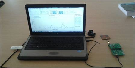
Figure 2. Experimental setup of AEERMS
The functioning of AEERMS is as follows: Initially, the required frequency is selected by using the display section of the PC loaded with CDEEC RF PC Client (Visual Basic 2010) software. The information about this frequency is sent to RF 2052 through the ARM controller. The RF 2052 then tunes its receiver to that frequency, so that it can be able to receive only those signals from the antenna in the range of centre frequency. The signals that are received by the RF 2052 is then given to Si 4362 where the strength of the signal is evaluated using ARM controller. The strength of the signal that is evaluated in Si 4362 can be viewed in the display section of the PC side. This is the radiated power in the corresponding frequency range from the particular antenna.
If the radiation level exceeds the desired limit, a short message will be sent to the corresponding authorities using GSM module indicating about the dangerous level of radiation from the cell site, so that it helps them to take necessary remedies to decrease the radiation from that particular cell site.
AEERMS is used in a variety of measurement campaigns. Initial Measurements for data verification and usage analysis were performed on cellular base station towers and also other sources of RF. A majority of cellular base stations exhibit near 100% power radiating during their busy operational hours. As part of AEERMS is monitoring 24x7 for all hours and also if the radiation is found to exceed the safety limits prescribed by the FCC, then it will send a message about exceeding the safety limits of radiation to concerned authority officers.
Radiation measurements were carried out at various places in Tirupathi, Renigunta and Madanapalli. Some of these readings are shown in figure below. It may be noted that on Tirupathi-Renigunta near Reliance mart on Bridge, the measured radiated power was as high as -26 dBm, which is equivalent to 70,686μW/m2 as there are 4 cell towers near reliance mart and near 100 meters distance Figure 3 shows the radiation measured using AEERMS, in the residential buildings within the distance of 150 metre from the cellular base station operating at GSM frequency of 1800 MHz (with Centre frequency 1850 MHz and frequency span 300 MHz requested by the user). From this figure, it is clear that the radiation level reaches a maximum of -38.5 dBm at the frequency 1874.107 MHZ.
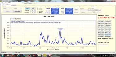
Figure 3. Radiated Power at GSM 1800MHz (busy traffic)
Using the AEERMS, the radiation measured at the place which is about 150 metre distance from the cellular base station, operating with 3G frequency 2100 MHz (with Centre frequency 2250 MHz and frequency span 500 MHz) is graphically represented in Figure 4. It is clear from this figure that, the maximum radiation level is -44 dBm at the frequency of 2165.179 MHZ.
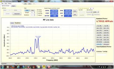
Figure 4. Radiated Power at 3G frequency 2100 MHz (busy traffic)
The AEERMS is capable of scanning all the available frequencies in its vicinity by selecting the all-mobile bands provided in the display module. Figure 5 shows the radiation level measured using this system in the 'all mobile bands' mode. It is clear from this figure that, the maximum radiation level -28.5 dBm exceeds the safety radiation limit -30 dBm at the frequency 2290.179 MHz. It means that the place is affected with danger level of electromagnetic radiation at this particular frequency. Also, the total radiated power detected by the AEERMS is 1.0268 μW which is hazardous level of electromagnetic radiation power in that location.
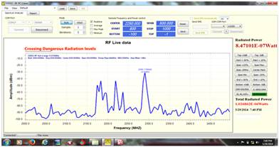
Figure 5. Radiated Power in the entire frequency band with an indication of danger level of radiation (busy traffic)
Using AEERMS, the radiation is measured in the close proximity (about 50 metre) of the cellular base station operating at GSM 1800 MHz frequency, and the received radiation is shown in Figure 6. From this figure, it is evident that the radiation level in the 50 metre radius is very larger (0dBm = 1 mW) than the safety limit -30 dBm (= 1 μW).
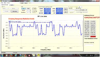
Figure 6. Radiated Power at GSM frequency 1800MHz (busy traffic)
The AEERMS is used to observe the electromagnetic signal strength during normal traffic conditions.
Figure 7 shows the measured radiation power during the normal traffic hours, at a distance of 150 m from the cellular base station operating at 3G frequency of 2100 MHz. It can be observed that, the power level observed in the normal traffic conditions is reduced by 10 – 100 times that of the busy traffic condition.
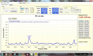
Figure 7. Radiated Power at 3G frequency of 2100 MHz (normal traffic)
The radiation power levels from a cellular base station observed during the normal traffic conditions at a distance of 150 m is shown in Figure 8. From this figure, it is clear that, the received power during the busy traffic hours is very larger than that of the normal traffic hours.
Figure 9 shows the measured total radiation power during the normal traffic hours, at a distance of 150 m from the cellular base station. It can be observed that, the total radiated power level observed in the normal traffic conditions is reduced by 10 – 100 times that of the busy traffic condition.
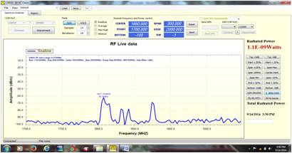
Figure 8. Radiated Power at GSM frequency 1800 MHz (normal traffic)
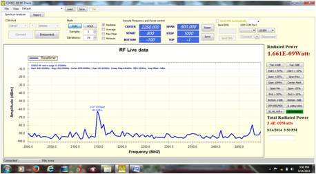
Figure 9. Total Radiated Power (normal traffic)
The AEERMS continuously compares the signal strength received from the IC Si4362 with the safety, radiation limits prescribed by the FCC, and if the received radiation power is more than the safety limits, it will activate the GSM module to send a message to the concerned authorities about the danger level of radiation at a particular frequency and place. Some sample snap shots of messages is shown in Figure 10.
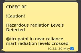
Figure 10. The alert message indicating harmful radiation at some place in Tirupati
The performance of the advanced embedded electromagnetic radiation monitoring system is evaluated by comparing its measurements with the known existing system for radiation monitoring. Here, the BSNL drive test is considered as the known existing system for electromagnetic radiation monitoring system to validate the measurements obtained by the AEERMS.
In the BSNL drive test, the system receives its own network signal from the mobile unit, which is connected to PC loaded with ACTIX Analyzer software. This software facilitates in graphical display of received power, call failures and call drops etc. of that particular network in that particular location. BSNL drive test can be operated in the frequency range of 800 MHz and 2.5 GHz.
Figure 11 shows a snap shot taken while comparing the measurements of the AEERMS with that of BSNL drive test.
A comparison is made between the results obtained using the AEERMS and the BSNL drive test performed at the frequencies 1800.6 MHz and 2156 MHz and are graphically represented in Figures 12 and 13. From these figures, one can observe the measurements obtained using the AEERMS agree with those obtained by using the BSNL drive test.
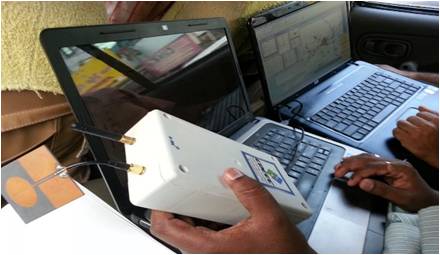
Figure 11. A snap shot while measuring the radiation using BSNL drive test
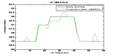
Figure 12. Comparison of results obtained by using the Proposed system (AEERMS) and the BSNL drive test at the frequency 1800.6 MHz
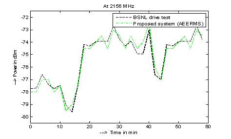
Figure 13. Comparison of results obtained by using the proposed system(AEERMS) and the BSNL drive test at the frequency 2156 MHz
It is observed from the graphical representations of the results that the radiated power received in both the cases is almost equal. Moreover, BSNL drive test is capable of detecting its operating frequency only, whereas the proposed system is able to receive the radiation power in the wide band of frequencies 30 MHz – 2.5 GHz. The fabricated antenna (Printed Elliptical Planar Monopole Patch Antenna) is capable of receiving the signals in the frequency range of1700MHz–2.5GHz.
The design and implementation of a system to monitor the electromagnetic radiation is emphasized more in this thesis work. The proposed electromagnetic radiation monitoring system is called advanced embedded electromagnetic radiation monitoring system.
Advanced embedded electromagnetic radiation monitoring system is designed to monitor the real time electromagnetic radiations produced by cellular base stations, mobile units, and the other RF sources. The designed system (AEERMS) is subjected to testing at different places, at different times (normal, busy), and it is observed that the system is able to detect the radiation corresponding to a particular frequency. Moreover, the AEERMS scans all the possible frequencies in its vicinity and thus measures the total radiated power corresponding to all the frequencies in the band 80 MHz – 2.5 GHz.
The performance of AEERMS is validated with BSNL drive test. The BSNL drive test has been carried out for one hour with GSM frequency 1800.6 MHz and one hour with 3G frequency 2156 MHz. From the BSNL test drive, it is observed that the designed system can sense the radiation power level as equal as that of BSNL drive test. Moreover, the BSNL drive test is limited to detect its operator frequency only, whereas, the proposed device can detect the radiation of the different cellular networks.
The AEERMS has the provision to send SMS to the Telecom authorities about the radiation level of the particular frequency at the particular place. Other electromagnetic radiation monitoring systems, except AEERMS have neither the details of the radiation corresponding to a particular frequency nor the SMS provision to inform the concerned authorities about the radiation level.
Following recommendations are made to reduce the effect of electromagnetic radiation.
1. The cellular base stations should be installed in such a way that, the minimum distance between individual base stations should be around 5 km.
2. The height of the cell tower antenna should be more than 50 m, if the base station is installed in the residential areas.
3. The Effective Radiated Power (ERP) of the cellular base station should be made as minimum as possible, to avoid the hazardous level of radiation.
This work has been supported by BSNL, Tirupathi.