[1]

The multiplier in any arithmetic unit dissipates significant amount of energy as large number of computations are required if the number of bits in the design increase. Thus, if efficient reversible logic is used, then the power consumption can be reduced drastically as the information bits are not lost in case of reversible computation. This paper focuses on the design of two-bit multiplier using a synthesis approach called Exorlink which reduces quantum cost compared to the technique Disjoint Sum of Products (DSOP). The design is coded in VHDL (VHSIC Hardware Description Language), simulated using ISim and synthesized using Xilinx ISE 10.1i for the device Spartan3E FPGA.
With the high demand of low power digital systems, energy dissipation in the digital system is one of the limiting factors. Reversible logic is one of the alternates to reduce heat/energy dissipation (R. Landauer, pg.1961) in the digital circuits and has a very significant importance in bioinformatics, optical information processing, CMOS circuit design, Nanotechnology, etc.
A reversible logic circuit (M.Bharathi, K.Neelima, 2012) (V.K.Puri, 2006, A.DeVos, 2010) has important features like usage of minimum number of reversible gates, garbage outputs and constant inputs. Among these, the minimization of the garbage outputs is one of the major goals in reversible logic design and synthesis. Each Reversible gate has a cost associated with it called as Quantum Cost, which is defined by the total number of elementary quantum gates needed to reali2ze the given function. The Quantum Cost (M. Bharathi, K. Neelima, 2012) of a circuit is proportional to the heat dissipation in the circuit. For any function realized using various types of gates, the Quantum Cost is given by the sum of the Quantum Costs of all the gates used to realize that function.
Arithmetic calculation is the one of the important part of any digital hardware. The squaring calculation has its own advantages in different fields like digital signal processing: Convolution, deconvolution, cryptography etc. where numbers of times we have to calculate fast square of the number. In order to calculate the square of the binary numbers, there are number of faster reversible multipliers by which we can calculate the square of the numbers. The reversible multipliers proposed in the literature are generally based on the recursive method. But, to design any of the digital hardware, the circuit complexity is one of the important measures which directly correlate with the delay. So, the main motivation behind this work is to investigate the implementation of efficient and low power squaring circuit architecture for the digital hardware industries (V.K.Puri, 2006).
In this paper, we are proposing a reversible 2–bit Multiplier circuit for the fast squaring calculation instead of using multiplier for the squaring which increases the complexity and the delay in the circuit. The design of new 2- bit binary multiplier circuit is used in most of the digital signal processing hardware using standard reversible gates. The designed multiplier circuit is having less garbage outputs, constant inputs, Quantum cost and Total logical calculation i.e. less quantum cost as compared to the Disjoint Sum of Products method (DSOP). The simulation results and quantized results are also shown in the paper which show greatest improvement in the design against the previous methodology.
In section 1, the existing method called DSOP method of computing quantum cost is discussed. Section 2 deals with the efficient method, Exorlink for evaluating the quantum cost. In section 3, the results are discussed and compared. Last Section concludes the paper.
The basic differences between the various definitions are given below.
A Boolean expression is an algebraic clause representing a relationship among a set of Boolean valued literals (P. Kemtopf (2002) Ning Song and Marek A. Perkowski 1996). A Boolean function can be represented by an equation containing Boolean expressions.
A Boolean expression containing a set of literals conjuncted together (i.e. ANDed) is called a Product/Cube.

The inclusive OR function in Boolean algebra is called Disjunctive Sum.

Two or more AND functions are ORed together to form a Sum-of-products expression. In this form, the product terms may or may not cover a common minterm..
Two cubes are said to be disjoint if their intersection of the set of minterms is null i.e., Disjoint cubes.
The distance of two min terms is the number of variables for which the corresponding literals have different sets of values.
i.e., the distance between 0011 and 0111 is 1
A cube cover corresponds to the familiar sum-of-products representation in Boolean Algebra with each cube corresponding to a product term and the function being the sum (logical OR) of those terms. Since a single cube represents a Boolean function on its own, the set of cubes representing a Boolean function need not necessarily be unique (C.H.Bennett, 1998). When each pair of cubes in the cover is disjoint, i.e., when the two cubes do not share a common minterm, is the case of interest. Such a situation corresponds to a Disjoint Sum-of-Products (DSOP) expression (M.Bharathi, Neelima Koppala, 2014).
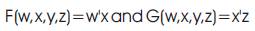
The example for conversion of SOP Expression to DSOP Expression (C.H.Bennett, 2014, Lokesh Shiva kumaraiah and Mitchell A. Thornton) is as shown in Figure1.
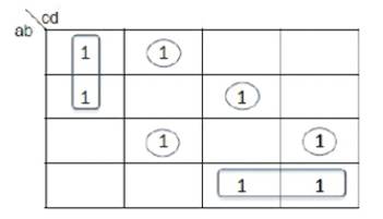
Figure 1. DSOP K-map for eq.6
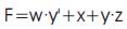
Let the Sum of Product Expression (Ning Song and Marek A. Perkowski 1996) be

Then the Disjoint Sum of Product Expression from Figure1 is given by eq.7.

Hence if no two product terms cover a common minterm, they are called a disjoint-sum-ofproducts (DSOP).
Exorlink Operation between two terms is as shown below
Eg.: 1011  0111 = x111
1x11
0111 = x111
1x11
x0x1 1001 = 0001 x01
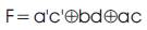
The Reversible Circuit's (M.Bharathi , K.Neelima , 2012, Mitchell Aaron Thornton, Rolf Drechsler and D.Michael Miller) DSOP and Exorlink equations are as shown in Figure 2 and Figure 3 respectively (M.Bharathi, Neelima Koppala, 2014) and their corresponding Quantum Cost is given below.
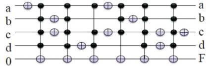
Figure 2. Reversible circuit for DSOP
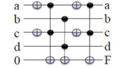
Figure 3. Reversible Logic for Exorlink
The DSOP Expression is given by

The Exorlink expression is given by
The process of converting the DSOP form to Exorlink form is shown in Figure 4 which includes 7 steps excluding the calculation of Quantum Cost.
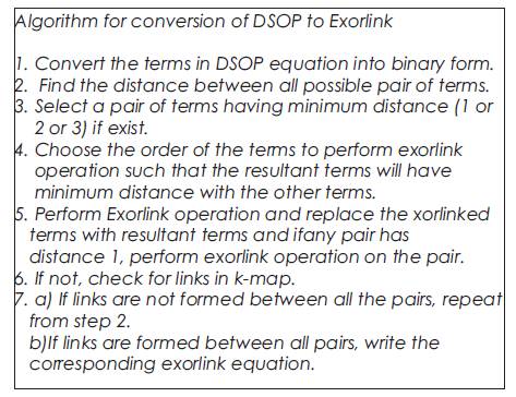
Figure 4. Algorithm for Conversion of reversible circuit from DSOP to Exorlink
A Full Adder is a combinational circuit that forms the arithmetic sum of three input bits. It consists of three inputs and three outputs (Ning Song and Marek A. Perkowski 1996). Two of the input variables denoted by A and B, represent the two significant bits to be added. The third input, represents the carry from the previous lower significant position.
Figure 5 shows the block diagram of 2-bit multiplier where A0, A1 --- multiplicand bits, B0, B1 --- multiplier bits and Z3, Z2, Z1, Z0 – output bits.
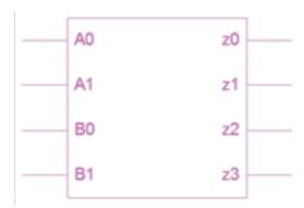
Figure 5. Block diagram of 2-bit multiplier
The truth table of 2-bit Multiplier is shown in Table 1.
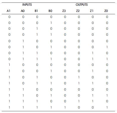
Table 1. 2-bit Multiplier Truth Table
From Table 1, the actual expressions relating to the output bits and input bits of multiplier and multiplicand are derived using SOP method in K-Maps. The related expressions are
SOP: Z3= A1A0B1B0
Z2 = A1A0'B1 + A1B1A0'
Z1= A1A0B0 + A1B1B0 + A1A0B1 + A0B1B0
Z0= A0B0
The corresponding DSOP and Exorlink based reversible circuit representations are shown below. Figure 6 shows the DSOP K-map for Z3 as a function of A1A0 and B1B0 inputs of multiplier and the corresponding DSOP reversible Circuit implementation is shown in Figure 7. The quantum cost of implementation is found to be 29.
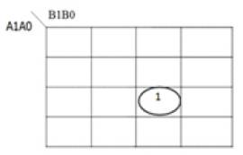
Figure 6. DSOP K-map for Z3
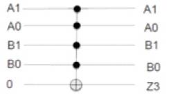
Figure 7. DSOP Reversible Circuit for Z3
Z3 :
DSOP: A1A0B1B0
Quantum Cost = 29
Figure 8 shows the Exorlink K-map for Z3 as a function of A1A0 and B1B0 inputs of multiplier and the corresponding Exorlink reversible Circuit implementation is shown in Figure9. The quantum cost of implementation is found to be 29.
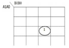
Figure 8. Exorlink K-map for Z3
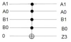
Figure 9. Exorlink Reversible Circuit for Z3
Exorlink: A1A0B1B0
Quantum Cost = 29
Figure 10 shows the DSOP K-map for Z2 as a function of A1A0 and B1B0 inputs of multiplier and the corresponding DSOP reversible Circuit implementation is shown in Figure 11. The quantum cost of implementation is found to be 46.
Z2 :
DSOP: A1A0'B1
A1A0B1B0’
Quantum Cost =4+13+29=46
Figure12 shows the Exorlink K-map for Z2 as a function of A1A0 and B1B0 inputs of multiplier and the corresponding Exorlink reversible Circuit implementation is shown in Figure 13. The quantum cost of implementation is found to be 34.
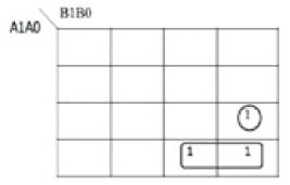
Figure 10. DSOP K-map for Z2
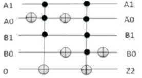
Figure 11. DSOP Reversible Circuit for Z2
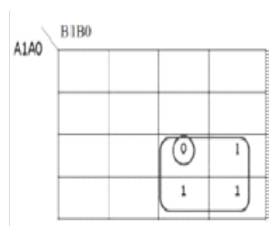
Figure 12. Exorlink K-map for Z2
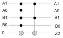
Figure 13. Exorlink Reversible Circuit forZ2
Exorlink: A1A0B1B0 A1B1
Quantum Cost = 29+5=34
Figure 14 shows the DSOP K-map for Z1 as a function of A1A0 and B1B0 inputs of multiplier and the corresponding DSOP reversible Circuit implementation is shown in Figure15. The quantum cost of implementation is found to be 92.
Z1 :
DSOP: A1B1'B0 A1'A0B1B0
A1A0'B1B0 A0B1B0’
Quantum Cost = 8+13+29+29+13=92
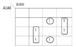
Figure 14. DSOP K-map for Z1
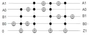
Figure 15. DSOP Reversible Circuit for Z1
Figure.16 shows the Exorlink K-map for Z1 as a function of A1A0 and B1B0 inputs of multiplier and the corresponding Exorlink reversible Circuit implementation is shown in Figure.17. The quantum cost of implementation is found to be 10.
Exorlink: A1B0 A0B1
Quantum Cost = 5+5=10
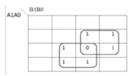
Figure 16. Exorlink K-map for Z1
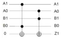
Figure 17. Exorlink Reversible Circuit for Z1
Figure18 shows the DSOP K-map for Z0 as a function of A1A0 and B1B0 inputs of multiplier and the corresponding DSOP reversible Circuit implementation is shown in Figure19. The quantum cost of implementation is found to be 5.
Z0 :
DSOP: A0B0
Quantum Cost = 5
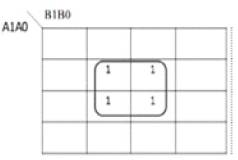
Figure 18. DSOP K-map for Z0
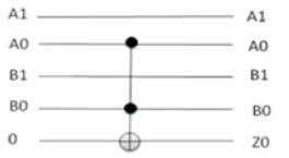
Figure 19. DSOP Reversible Circuit for Z0
Figure 20 shows the Exorlink K-map for Z0 as a function of A1A0 and B1B0 inputs of multiplier and the corresponding Exorlink reversible Circuit implementation is shown in Figure 21. The quantum cost of implementation is found to be 5.
Exorlink: A0B0
Quantum Cost =5
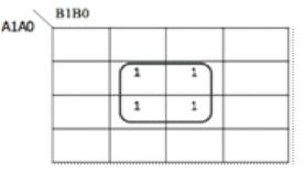
Figure 20. Exorlink K-map for Z0
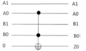
Figure 21. Exorlink Reversible Circuit for Z0
Thus from Table 2, it is clear that there is a drastic decrease in the Quantum Cost for Exorlink when compared to DSOP for a 2-bit reversible multiplier. Hence Exorlink based multiplier design is the one with more power efficient operation, as it can link any two cubes in an array of cubes having any arbitrary distance. Also, when compared to the DSOP logic, the output bits of multiplier realized by Exorlink can have fewer gates, fewer connections and less Quantum Cost.
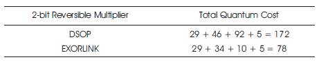
Table 2. Total Quantum Cost for 2-bit Multiplier
Exorlink logic employed in the design of multiplier proves to be the more power efficient method in Reversible logic synthesis. It can link any two cubes in an array of cubes of an arbitrary distance. Hence by using this method, a large number of variables in the expression gets minimized, thereby reducing the Quantum Cost compared to the Disjoint- Sum of Products (DSOP). Employing Reversible Logic and optimizing the Quantum Cost by using Exorlink technique reduces the heat dissipation in the circuits which leads to new approach for Integrated Circuit design and helps in continuing Moore's Law. The designed multiplier circuit is proved to have less garbage outputs, constant inputs, Quantum cost and Total logical calculation i.e. less quantum cost as compared to the Disjoint Sum of Products (DSOP) method.