Figure 1. The H2O RFC System
Based on a technology that separates power conversion and energy storage, fuel cell energy storage enables each function to be separately tuned for performance, cost, or other key variables. This capacity to tune every component of an energy storage system might provide considerable advantages for many uses. Here, different fuel cell-based energy storage systems are discovered that use hydrogen as the energy storage medium. Electrolyzes are fully regenerative fuel cell systems that are relevant for Polymer Electrolyte Membrane (PEM) fuel cells. The technological and product development status of these systems and the state of various hydrogen storage technology choices will be discussed.
Due to its high fuel conversion efficiency, friendliness with the environment, and dependable, quiet operation, fuel cells are increasingly being acknowledged as the preferred type of electricity generation for distributed power generation. Fuel cells play significant roles in both conventional and novel energy storage applications and are increasingly acknowledged as the ideal technology for direct energy conversion.
When used as an energy storage device, a fuel cell is combined with a fuel production device, commonly an electrolyzer, to create a Regenerative Fuel Cell (RFC) system that can convert electrical energy into a storable fuel and then use that fuel in Fuel cell reactions to provide electricity if needed. The most common types of proposed RFCs use hydrogen as the energy storage medium, which is produced by the electrolysis of water. This RFC hydrogen-oxygen cycle and possible applications of this technology for traditional energy storage applications are explored here.
The ability to isolate the energy storage function from the energy conversion function and optimize both is essential to the RFC system's efficiency. A tiny fuel cell with this power rating can be placed within the computer center near to the load, for instance, if a computer installation needs a backup power level of 5 kW. Numerous kilowatthours of energy required outside the structure might be securely stored outside as hydrogen. When electricity is provided to the fuel cell, hydrogen, the load might operate at full capacity for several days. Therefore, there would always be a positive indicator of the charge that was still in the battery, as determined by the quantity of hydrogen that was still in the tank, as shown by the pressure. As a consequence, a system that offers complete backup power for protracted periods of time is created, with hydrogen serving as the energy storage medium and being securely kept outside the structure. The device contains substantial volumes of lead and acid when a similar quantity of energy is stored using conventional lead-acid batteries, which necessitates a regulated environment (Colbourn, 1999).
The stored hydrogen would not be affected by temperature, storage time, or the number of storage cycles and could be completely discharged without any degradation over its lifetime. When the tank needed to be recharged, it could be recharged by electrolyzing water with power from the primary energy source.
While this potential of RFCs has been studied for many years, RFCs have not found practical application. However, recent developments in the state of Polymer Electrolyte Membrane (PEM) water electrolyzers are creating new possibilities, and fuel cells, especially PEM fuel cells, are becoming more and more cost-effective, driven by the needs of the automotive industry. Similar progress has been made in reducing the cost of PEM electrolyzers through commercialization to serve the industrial gas market (Smith, 2000).
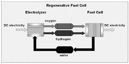
Using the H2O cycle as an energy storage medium, RFC is an elegantly simple concept. Various other hydrogen vapors have also been proposed that have advantages in specific applications, but the H2O cycle has highly acceptable performance characteristics suitable for widespread use as a backup or premium power system and has a minimal environmental impact. This H2O RFC is shown schematically in Figure 1. As shown here, water is electrolytically decomposed into hydrogen and oxygen. Hydrogen is stored, while oxygen can be stored for remote or extra-terrestrial applications or vented to ambient air. When energy is needed, the hydrogen is simply fed into the fuel cell, and electricity is produced. This approach ensures that the fuel cell always has a supply of pure, fuel cell-compatible hydrogen, pressurized and ready for use.
Figure 1. The H2O RFC System
The only inputs required are electrical power, make-up water, and air for reactant and cooling. When oxygen is stored and used as a reactant, the need for ambient air and make-up water can be eliminated while increasing efficiency. The key elements of the RFC are,
The electrolysis subsystem is key to RFC functionality, as this system must both generate and compress hydrogen for easy storage. While water electrolyzers that use a liquid caustic electrolyte have been available for many decades, these conventional liquid electrolyte water electrolyzers have been limited by its absolute and differential pressure capabilities. PEM water electrolyzers similar to the widespread PEM fuel cell are available that generate and store hydrogen at pressures suitable for storage in either conventional tanks or metal hydrides.
The operation of this PEM electrolyzer is shown in Figure 2 and the water is introduced into the anode, where it is electrolytically decomposed into oxygen, protons, and electrons. Oxygen is evolved as O gas at the electrode 2 surface while protons are driven through the membrane; electrons move around the outer circuit. At the cathode, protons combine with electrons to form hydrogen gas. Since a solid electrolyte is used, no acidic or corrosive material can contaminate the gas or the system, and the solid electrolyte also promotes gas generation directly under pressure. Typical cells can generate hydrogen at pressures up to 200 psi without a compressor while maintaining oxygen at ambient pressure, and pressures up to 6000 psi have been reported. The additional energy, the Nernst voltage, above that required for electrolysis is relatively small, approximately 30 mV per decade of pressure increase. This results in electrolysis surges of only 0.030 V per cell to pressurize from 1 to 10 bar and only 0.60 V per cell to pressurize from 1 to 100 bar.
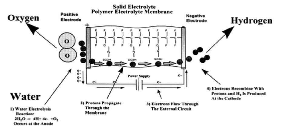
Figure 2. PEM Electrolysis Cell Cross-Section
PEM electrolyzers were first developed in the 1970s and have been available for many years, primarily for military and aerospace applications for generating life support oxygen aboard nuclear submarines, refueling high pressure oxygen aboard commercial aircraft, and manufacturing oxygen to support life aboard the International Space Station (Smith et al., 1994 ). Recently, PEM electrolyzers have been developed for commercial use to supply hydrogen to the industrial gas industry for use as a process gas in various manufacturing applications. Although this commercial production of PEM electrolyzers is not specifically tailored to energy storage needs, it serves as a basis for cost reduction through serial production of the basic elements of the electrolysis system. Systems such as the HOGEN® series of electrolyzers manufactured by Proton Energy Systems are now commercially available in sizes to produce 0.5, 1.0, and 10 Nm3 of hydrogen per hour.
The PEM fuel cell is now widely promoted as the preferred low-temperature energy conversion device, and the PEM fuel cell cross-section is shown in Figure 2.
In a fuel cell reaction, hydrogen and oxygen are fed to the electrodes, electricity is produced, and water is produced as a by-product of the reaction. While the performance issues related to PEM fuel cells for conventional applications such as automotive, residential, etc. are well documented, additional issues arise when it is used in RFCs. Problems arise regarding electrode reversibility and water management. Catalysts must not be affected by the direction of the reaction, and water must be supplied to the cell in electrolysis mode while water must be removed in fuel cell mode to avoid flooding the cell. Other system problems exist with respect to the reversibility of system elements and the choice of reactants. In a practical system, the RFC should be capable of using either H2-O2 or H2-air and should be able to operate at higher pressures than those normally associated with conventional fuel cells (Butler et al., 1996).
Much has been published on the development of conventional PEM fuel cells; it is enough to recognize that this high degree of development creates a supportive environment with advances in membrane, catalyst, cell structure, etc. These hydrogen-air or reformate-air PEM fuel cells are now in full development, with various organizations aiming for commercial sale at prices up to $50 per kW for automotive applications or less than $500 per kW for stationary applications. All of these systems are designed to act as fuel-to-power devices, but it can be operated from a stored hydrogen source and, in a very high-end integration, could be used as an element of an RFC fuel cell (Dyer, 1999).
With support from the National Aeronautics and Space Administration (NASA) and the Electric Power Research Institute (EPRI), Proton Energy Systems has been developing Unitized Regenerative Fuel Cell (URFC) technology since 1998 to function as a URFC. In this regard, the cell piping was modified to accommodate new coolant passages and cell flow field structures, and Membrane Electrode Assemblies (MEAs) designed for the reversible operation were incorporated into the cell assembly. The specific stack of cells used for testing is shown in Figure 3.
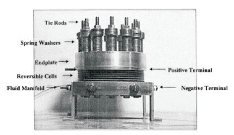
Figure 3. The UNIGEN Cell Stack
This cell assembly design is capable of operating at pressures over 150 psi. Cells can be added to the stack based on system output voltage requirements or required charging speed. This test cell design was assembled, checked, and mounted in the test system prior to operational testing.
UNIGEN performance testing was initiated using a single cell operating under various conditions to establish a per formance baseline. These data resulted in polarization curves collected at different pressures and temperatures. Figure 4 shows polarization curves detailing the relationship between cell current density and voltage for single-purpose fuel cells and electrolysis systems using Nafion 117, a commercially available polymer electrolyte membrane. Importantly, the data presented in these polarization curves show that Proton's URFC performs as well as dedicated electrolyzers and fuel cells at 120 °F under similar pressure conditions ( Smith, 2000; Nojavan et al., 2017).
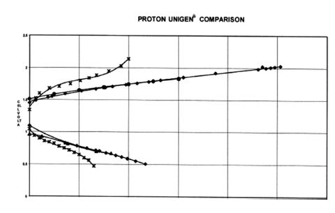
Figure 4. Proton UNIGEN Comparison
In Figure 4, UNIGEN fuel cell and electrolysis data were collected at 119°F and respective operating pressures of 50 psi O2 and 40 psi H2 . This polarizer set was compared to a set of dedicated electrolyzers (119°F 200/150 PSIG H2/O2 ), a primary fuel cell (120°F 80/85 PSIG H /O ), and another URFC operating at 120°F 40/50 PSIG H2/O2. This comparison shows that Proton UNIGEN performs almost the same as a dedicated electrolyzer and fuel cell. It should be noted that the dedicated fuel cell actually operated at a higher pressure, 80/85 PSIG H2/O2, while the Proton UNIGEN was tested at 40/50 PSIG H2/O2. Fuel cell performance is expected to increase with higher reactant inlet pressures. In the same chart, Proton UNIGEN is compared to another URFC operated at Lawrence Livermore National Laboratory (LLNL). In this comparison, it is clear that the Proton UNIGEN outperforms the LLNL URFC at identical reactant pressures of 40/50 PSIG H2/O2 and similar temperatures.
One of the key challenges in implementing RFCs for energy storage is the development of a compact, reliable system that can implement a reversible cycle. In this regard, the EPRI and NASA programs included the development of integrated test cells. Each of these systems includes all mechanical and electrical controls required for fully automatic, reversible operation as well as onboard hydrogen storage.
The Electric Power Research Institute (EPRI) system is a cycle and passive dewatering fuel cell water removal system with liquid water feed and electrolysis with active cooling. In contrast, NASA's test unit was designed as a zero-gravity-compatible, water-fed static electrolyzer with passive cooling that reduces system complexity and parts count.
Electric-to-electric cruise efficiency calculations have been completed to compare the Proton UNIGEN with another URFC and a dedicated fuel cell or dedicated electrolyzer. This comparison can be seen in Figure 5.
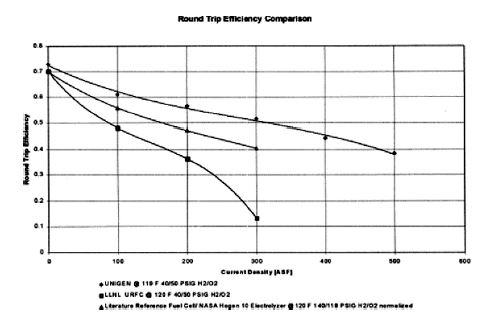
Figure 5. URFC Round Trip Efficiency
The reverse efficiency of the process is simply the total efficiency of the electrolysis process multiplied by the total efficiency of the fuel cell process. The calculation assumes an equivalent distribution of operating time between fuel cell and electrolytic cell operations. Round trip efficiency calculations were performed using data under the following conditions: UNIGEN (119°F, 40/50 PSIG H2/O2 ), LLNL URFC (120°F, 40/50 PSIG H2/O2), and Reference Fuel Cell/HOGEN ® 10 Combination Electrolyzer (120°F, 140/118 PSIG H2 /O2 normalized).
The calculations determine the reverse efficiency of electrolysis and fuel cell processes.
The voltage efficiency of the electrolysis process is defined in Equation 1.
Veff=Thermal Neutral Voltage/Cell Voltage eff =1.53/V
The current efficiency of the process is defined in Equation (2).
I eff = (Cell Current Density – Diffusion Losses)/Cell Density eff = ASF-ASF O2 +ASF H2 /ASF
Gas diffusion losses are defined from the parametric relationship that follows for Nafion 117.
In Equations 3 and 4, ASF H2 and ASF O2 are permeation losses in amperes per square foot. T is the temperature in degrees Fahrenheit, and P is the gas pressure in Pounds per Square Inch Absolute (PSIA). The overall efficiency of the electrolysis process is equal to the voltage efficiency multiplied by the current efficiency.
ASF O2 =(1467/(348-T)-3.7)*P/132.26
ASF H2 = (2561(421-T)*P/132.26
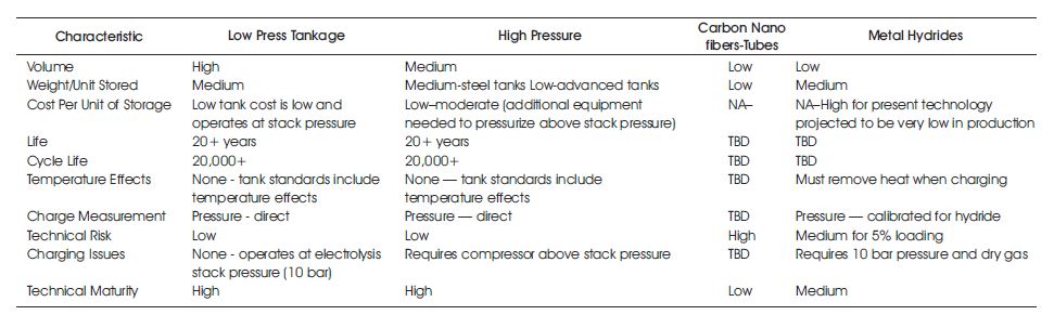
Table 1. Hydrogen Storage Technology Comparison
Using modified liquid propane tanks for hydrogen is a highly viable and cost-effective option that has now proven itself over many years of application in industrial gas companies. For example, Brown Industries of Salina, Kansas, has installed over 50 large low-pressure liquid propane tanks that are now used for hydrogen storage and have over 15 years of reliable operation. Given the highly advanced state of the liquid propane tank industry and the long-term success of using these tanks for hydrogen, this form of storage appears to be a cheap and practical way to store hydrogen in an RFC system.
The RFC implementation using hydrogen as an energy storage medium provides a method of energy storage that has many advantages. Energy stored as hydrogen can be stored for long periods of time and is not sensitive to cycle life, temperature, or self-discharge. Table 2 highlights the comparative performance of URFCs compared to conventional batteries. Cost figures are based on a 200 kWh RFC system supplying a 2 kW load and an equivalent set of Gould National Batteries (GNB) Absolyte lead-acid batteries typically used for renewable energy storage systems.
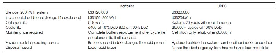
Table 2. RFCs Significant Advantages Over Batteries for Many Applications
These benefits can both improve the usability of energy storage for existing applications and create new opportunities. RFCs used as backup or backup power systems can provide a higher degree of utilization than conventional battery packs by providing longer periods of backup power with less impact on the installation at a lower cost. In grid-connected applications, storing large amounts of energy without lifetime or life-cycle limitations allows RFC to support utilities through distributed load management. In such applications, RFC generates and stores hydrogen during off-peak hours and produces electricity during peak periods.
In off-grid applications such as photovoltaic or windbased systems, batteries coupled to a diesel generator commonly provide power for dark or low-wind conditions. In such an application, the batteries supply power until the stored energy is exhausted, then the generator provides additional power by recharging the batteries. For these off-grid applications, RFC could replace most batteries and greatly reduce or eliminate the need for a backup generator. If the RFC was coupled with a reformer that could use hydrocarbon fuel, the generator hardware could be completely eliminated, while the use of stored hydrogen as the primary energy storage medium would minimize the logistical replenishment of backup hydrocarbon fuel (İnci et al., 2021).
As shown in Figure 6, URFC can achieve a significant cost advantage where the amount of stored energy is high relative to the instantaneous output from the fuel cell. This relationship applies to a wide range of conditions. Figure 6 illustrates the life cycle cost to energy stored relationship for a 2 kW power source compared to conventional Absolyte lead-acid batteries. As shown in Figure 6, the cost difference can be quite dramatic as the amount of energy stored increases, but batteries show favorable characteristics as the energy-to-power ratio (kWh/kW) decreases. In developing these projections, the end-user price paid for a 2 kW fuel cell is estimated to be $1000 per kW, and the cost of energy storage is estimated to be $20 to $30 per kWh. Energy storage figures are derived from actual low-pressure tank quotes for small (1–10) purchases.

Figure 6. 10-Year Life Cycle Cost Comparison of URFC and Batteries
Fuel cell estimates are for advanced production based on Proton Energy Systems' internal projections for this size unit and represent the price paid by the end-user including distribution surcharges (Smith, 2000).
While lead-acid batteries are now the mature and dominant energy storage technology, the H2 O2 RFC is only one of many emerging energy storage technologies that are being actively developed, that includes,
These technologies cover a wide range of power and energy applications, from conventional standby duty to providing very high levels of power delivered for short periods of time, such as superconducting storage. Table 3 summarizes these technologies together with the H2 O2 RFC with respect to several key parameters.
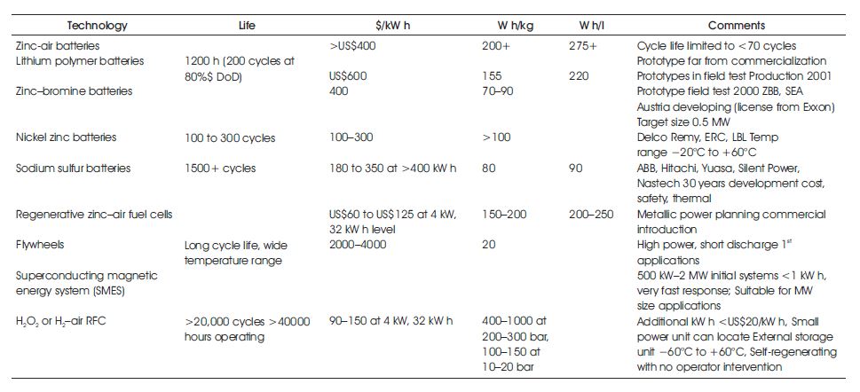
Table 3. The H2 O2RFC and Other Emerging Energy Storage Technologies
A number of other technologies also offer the promise of improved energy storage capability, but only the RFC technologies, in the Zn–Air and Hydrogen–Air configurations, offer the promise of true low-cost, highcapacity systems due to the separate optimization of power and energy functions (Peters et al., 2020).
RFC is being rapidly developed to be able to provide high levels of energy storage capability at a fraction of the cost of conventional lead-acid batteries and could reach commercial viability earlier than many PEM fuel cell architectures that require reformed hydrocarbons. This is due to the low cost and high availability of medium-pressure hydrogen storage, recent advances in self-pressure PEM electrolyzers, and the rapid development of primary and reversible PEM fuel cell systems. Two of the three key elements of the RFC, the PEM electrolyzer and the hydrogen storage, are now commercially available, and the last element, the fuel cell or reversible cell, is being rapidly developed. Hydrogen storage in medium-pressure tanks is costeffective but limited by tank size; it is suitable for remote or industrial applications. The development of the ability to generate high-pressure and solid-state low-pressure storage in hydrides or carbon will increase wide acceptance and use.