Figure 1. System Structure
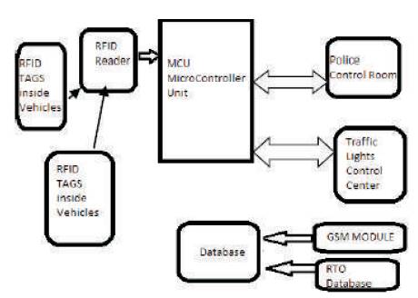
Indian traffic is non-lane based and chaotic. In recent years, wireless networks are widely used in the road transportation. The proposed system tracks the location of an emergency vehicle, and provides a green wave to the vehicle. Implementation is adopted using RFID transponders, tags, readers, and wireless technologies. RFID is a profitable system which will provide uninterrupted wireless communication in the network even in all conditions. RFID technology allows several items to be quickly scanned, enabling fast identification of a particular ambulance in the lane and also the stolen vehicles, even when it is surrounded by several other items and proximity sensors to calculate the count of normal vehicles was not attempted in traffic control. RFID access control system controls the entire operation by using RFID readers and RFID tags and processes them into the wireless network by using GSM technology, the type of modem to access the speed of operation without delay by using ZigBee, operating at low-power to perform predefined tasks at all the levels of work configurations. Therefore the proposed system provides a simple, low- cost, and real time smart traffic light control system that aims to overcome many defects and improve the traffic management.
Traffic lights, developed since 1912, are signalling devices that are conceived to control the traffic flows at road intersections, pedestrian crossings, rail trains, and other locations. Traffic lights consist of three universal colored lights: the green light allows traffic to proceed in the indicated direction [11], the yellow light warns vehicles to prepare for short stop, and the red signal prohibits any traffic from proceedings [4]. Nowadays, many countries suffer from the traffic congestion problems that affect the transportation system in cities and cause serious dilemma. In spite of replacing traffic officers and flagmen by automatic traffic systems, the optimization of the heavy traffic jam is still a major issue to be faced, especially with multiple junction nodes. The rapid increase of the number of automobiles and the constantly rising number of road users are not accompanied with promoted infrastructures and with sufficient resources. Partial solutions were offered by constructing new roads, implementing flyovers and bypass roads, creating rings, and performing roads rehabilitation.
However, the traffic problem is very complicated due to the involvement of diverse parameters. First, the traffic flow depends on the time of the day where the traffic peak hours are generally in the morning and in the afternoon. Secondly, the current traffic light system is implemented with more delays where the lights transition time slots are fixed regularly and do not depend on real time traffic flow. The third point is concerned with the state of one light at an intersection that influences the flow of traffic at adjacent intersections. The conventional traffic system does not consider the case of accidents, road works, and breakdown cars that worsen traffic congestion. In addition, a crucial issue is related to the smooth motion through intersections of emergency vehicles of higher priorities such as ambulances, rescue vehicles, fire brigade, police, and VIP persons that could get stuck in the crowd. Finally, the pedestrians that cross the lanes also alter the traffic system [1].
The conventional traffic system needs to be upgraded to solve the severe traffic congestion, alleviate transportation troubles, reduce traffic volume and waiting time, minimize overall travel time, optimize cars safety and efficiency, and expand the benefits in health, economic, and environmental sectors. This proposed system provides a simple, low-cost, and real time smart traffic light control system that aims to overcome many defects and improve the traffic management. The primary objective is to identify the emergency vehicle and track its location so that we can provide a green wave to the emergency vehicle. Conventional technologies use image processing systems to identify the emergency vehicle. But these systems have a drawback during bad weather conditions. Due to wind, rain, fog, etc., the image received by the camera is distorted by noise and it becomes difficult for the system to identify the desired vehicle. Thus, the proposed system uses RFID transponders and readers. The advantage of RFID is that it is a cost effective system which will provide uninterrupted communication in the network even in bad weather conditions [2]. Though RFID tags and proximity sensors are used in many applications, they are not used specifically in traffic control systems. The use of RFID tags to identify the presence of an ambulance in a lane and proximity sensors to calculate the count of normal vehicles was not attempted in traffic control [5]. A GSM modem is a specialized type of modem, which accepts a SIM card and operates over a subscription to a mobile operator, just like a mobile phone. The ZIGBEE operates at low-power and can be used at all the levels of work configurations to perform predefined tasks [2].
The basic block diagram of the system is illustrated in Figure 1. The system comprises of a RFID reader and a RFID tag or transponder [9]. The proposed system uses a high frequency reader which will provide long range to the system. During the manufacturing of vehicles, passive tag or transponders are embedded inside the dash board of the vehicle such that it is not easily visible to human eyes. During the registration of the vehicle, each vehicle gets a unique license plate number. In this system a database is maintained, in which table comprises of information like Unique ID of tag against which the vehicle license plate number and its category is stored. The proposed system defined three categories for different types of vehicles, namely Emergency vehicle, Stolen Vehicle, and a Normal Vehicle. A Column of priority is also added in table, in which three levels are defined: low, high and highest.
Figure 1. System Structure
A priority “T” for stolen vehicles. However, as per the demand of the user, more levels and categories can be added easily [14]. Readers are installed on every junction of the city, on top of the roads. The reader reads the unique ID present on the tag or transponder and sends the information to the main system to check its category and priority in the database and take the desired action accordingly. For immediate update of category of vehicle and also its priority level, the database is connected to the GSM module [4]. The RTO database is also connected to the main database, so that regular updating of the system database can be done. As soon as the vehicle is registered with Regional Transport Office (R.T.O), the vehicle is registered with the system as well. The microcontroller unit is connected to the police control room, to send the alert signals of any stolen vehicle detected [3], [8].
The system has three predefined categories of vehicle namely, normal vehicle, stolen vehicle, and emergency vehicle. These categories can be changed as per the requirements. The updating of the priority can be done dynamically with the help of the GSM module as shown in the system structure block diagram of Figure 1.
There are three levels of the priority of the vehicle defined in the system namely low, high, and highest. For stolen vehicles the priority is set as 'T' [4].
The database of the system is connected with the GSM module, so, the information regarding the category and priority of vehicles can be easily updated in seconds through a Short Messaging Service (SMS) [12].
All the information of the vehicles passing through the junctions is also stored in the system database, which could be used at a later stage for traffic monitoring and other purposes [14].
Readers will be installed before every traffic light junction such that the direction of movement of stolen vehicle is easily detected. Readers will be installed over the road at a certain height. Readers need to be protected from direct sunlight and rain, so, they need to be covered.
In these methods there are mainly three modules as follows:
Figure 2(a) shows the module for experiment purpose, passive RFID tags, and RFID reader with frequency 125 KHz. RFID tag are used, when vehicle comes in the range of the receiver transmits a unique RFID to the reader. The microcontroller connected to the RFID reader will count the RFID tags read in 2 minute duration [5]. For testing purpose, if the count is more than 10, the green light duration is set to 30 seconds, if count is between 5 and 9, the green light duration is set to 20 seconds. If the count is less than 5, the green light duration is set to 10 seconds. The red light duration will be for 10 seconds and orange light duration will be for 2 seconds [6].
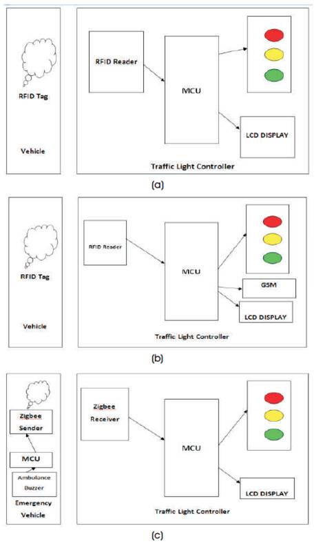
Figure 2 (a) Automatic Signal Control System, (b) Stolen Vehicle, (c) Emergency Vehicle Clearance
As shown in Figure 2(b), in this module, for testing purpose, the unique RFID tag read by the RFID reader is compared to the stolen RFIDs stored in the system. If a match is found, then the traffic signal is immediately turned to red for a duration of 30 seconds. Also an SMS is sent specifying the RFID number by using SIM300 GSM module.
In Figure 2(c) shows the Emergency Vehicle Clearance module. In this module, there are 2 parts, first part which is ZigBee transmitter is placed in the emergency vehicle. When the switch is pressed, it will transmit the signal. The signal contains unique id and security code. The transmitter contains PIC16F877A microcontroller and ZigBee module [10]. The microcontroller sends the commands and data to the ZIGBEE via serial communication. Second part is the receiver, which is placed at traffic pole. It also contains MCU and ZigBee module. The receiver compares the security code received to the security code present in its database. If it matches, then it will turn the green light on.
First, the receiver part is turned on. The red and green signal will be on for 10 seconds duration and orange light will be on for 2 seconds duration one after the other. Secondly, we bring the RFID of stolen vehicle into the range of RFID reader. Then the signal will turn to red for duration of 30 seconds and a SMS is received. Thirdly, we bring 12 RFIDs into the range of RFID reader, and then the green light duration will change to 30 seconds. Fourthly, an emergency vehicle carrying ZigBee transmitter into the range of ZigBee receiver [12], and then the traffic light will change to green till the receiver receives the ZigBee signal [6].
In the default condition, red and green light will set for 10 seconds. The time period will be varied according to the traffic conditions, stolen vehicle, and emergency vehicle [7].
The overall system hardware contains the following.
A Radio Frequency Identification Tag (RFID tag) is an electronic tag that exchanges data with a RFID reader through radio waves. Most RFID tags are made up of at least two main parts. The first is an antenna, which receives Radio Frequency (RF) waves. High frequency RFID readers are installed above the roads prior to every traffic light system in all directions in such a manner that the entire area comes under the range of RFID reader [13].
A passive Ultra High Frequency (UHF) Radio Frequency Identification (RFID) transponder has been used in the system. The RFID Transponders technology will play an important role in the field of automatic identification, and Passive RFID transponders are installed inside every vehicle at the time of manufacturing. RFID transponders consist of a unique ID. Once the vehicle is registered and gets the license plate number, its data is stored in the database along with the category of the vehicle, either regular or Emergency, which could be changed to any other category as per the requirements [14].
The Base station is equipped with a microcontroller unit connected to the database, consisting of all the information. The database is connected to the GSM module which helps in immediate update of the database. The RFID readers are connected to the base station with the help of XBEE transceivers. The readers will keep on sending the Unique Identification (UID) of the vehicle from every traffic light to the Microcontroller Unit (MCU). The MCU will then check for the category and the priority of vehicle in the database and will accordingly send outputs to the traffic lights and Police Control Room [15].
An user interactive interface for user vehicle is also available, in which the driver of the emergency vehicle will update the priority of vehicle. As in most cases, if there is no patient in the ambulance, its default priority level will be set to low. This interface also helps the driver to select the junctions through which the emergency vehicle will pass. The priority of the vehicle, location, and the total number of junctions to be passed through are sent to the system with the help of a GSM module [12]. This data is received by the GSM module of the system and the database is updated.
Therefore the conclusion of this project with automatic traffic signal control based on the traffic density in the route is that the manual effort on the part of the traffic policeman is saved. As the entire system is automated, it requires very less human intervention. With stolen vehicle detection, the signal automatically turns to red, so that the police officer can take appropriate action, if he/she is present at the junction. Also SMS will be sent so that they can prepare to catch the stolen vehicle at the next possible junctions. Emergency vehicles like ambulance, fire trucks, need to reach their destinations at the earliest. If they spend a lot of time in traffic jams, precious lives of many people may be in danger. With emergency vehicle clearance, the traffic signal turns to green as long as the emergency vehicle is waiting in the traffic junction. The signal turns to red, only after the emergency vehicle passes through.
Further enhancements can be done to the prototype by testing it with longer range RFID readers. Also GPS can be placed into the stolen vehicle detection module, so that the exact location of stolen vehicle is known. Currently, authors have implemented system by considering one road of the traffic junction. It can be improved by extending to all the roads in a multi- road junction. The proposed system can also be extended to provide the traffic density database to cloud server at different traffic signalling areas, so that the users can also select the path which is having less traffic.
The authors express their gratitude to SVCET (Autonomous) College & Management, for guiding them the way. They also thank the Department of Electronics and Communication Engineering for providing labs to develop this prototype. Finally, they thank the final year student Poorna Chandra, who supported in developing this system.