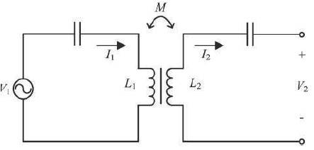
Figure 1. Basic Circuit Model of Wireless Power Transfer System
In this paper the design of roadway powered online electric vehicles by using wireless power transfer system is presented. Electric vehicles are charged on the roadway during their motion by the Wireless Power Transfer technology. Wireless Power Transfer (WPT) is the process of transferring power from transmission part into receiver part without passing through any man-made conductive elements interconnecting them. Online electric vehicles works on the principle of ElectroMagnetic Induction (EMI). Electromagnetic Inductive Power Transfer (IPT) is a popular technique of transferring power wirelessly over a short range. The result to be expected in this system is 80% of power transfer efficiency below 26 cm air gap.
The environment pollutions are caused by combustion engines, together with the depletion of fossil fuels (such as coal, oil, or natural gas) that is formed in the earth from plant or animal remains. Electric vehicles are considered as an alternative to vehicles with combustion engine [1]. Electric vehicle technology has been developed to decrease the uses of fossil fuel in vehicles. However, all-electric vehicles, such as plug-in electric vehicles and battery electric vehicles, are distributed narrowly at present owing to some battery-related drawbacks such as large size, heavy weight, high price, long charging time, and short driving range. These problems are not easily solved by current battery technology [3]. To address battery problems, the concept of roadway-powered electric vehicles has been proposed. The electric vehicles are charged on the road by wireless power charging, and the battery can hence be downsized and no waiting time for charging is needed [4].
A contactless power transfer system uses inductive coupling [2]. One of the most important factors that must be considered in designing an inductive coupling system is the target power of the system. Voltage and present ranges, usable devices, and operating frequency of the system depend on the target power [6]. The Wireless Power Transfer system for running electric vehicle is a public service system that is installed on a road; the use of the resonance frequency must be permitted by the government. Generally, Wireless Power Transfer systems for electric vehicles use 10-100-kHz frequency. In the OLEV system, the target power is 100 kW, and the resonance frequency is 20 kHz [10].
The basic circuit of the Wireless Power Transfer system is shown in Figure 1, where I1 , I2 represent the current sources of primary and secondary windings; V1 , V2 represent the voltage sources of primary and secondary windings; L1, L2 represent the mutual inductance. This circuit is fundamentally same as the circuit model of transformers. In the circuit, a larger mutual inductance M facilitates more effective power transfer [8].
Figure 1. Basic Circuit Model of Wireless Power Transfer System
Equation (1) represents the mutual inductance M is determined by L1 , L2 , and the coupling coefficient k, as follows:

where k indicates the degree of coupling strength and is between zero and one. However, k of a Wireless Power Transfer system for moving electric vehicles is very small due to the large air gap distance between the bottom of a vehicle and the road, which is necessary for safe driving.
Figure 2 represents the conceptual diagram of online electric vehicle system. A contactless power transfer system consists of a power transmission and reception parts. The power transmission part is composed of an inverter and power lines [5]. The inverter provides power, and the power lines carry current and generate magnetic flux [7].
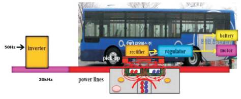
Figure 2. Conceptual Diagram of OLEV System
The power reception part is composed of pickup modules, rectifiers, and regulators. The pickup modules generate power from induced voltage and current, the rectifiers convert AC power to DC, and the regulators control the output voltage, which is input to batteries and motors [9].
The power transmitters are inductive cables buried under the roadways which provides a magnetic field to supply enough power to the vehicle with required energy. The power receiver part mounted below the vehicle remotely collects electricity and distributes the power either to operate the motor in the vehicle or to charge the battery. Whether running or being stopped, the online electric vehicle continuously collects electric power over the subversive cables. The result of online electric vehicle mitigates the problem of providing the electric vehicle with heavy and massive batteries. Figure 3 shows the block diagram of online electric vehicle system.
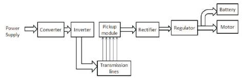
Figure 3. Block Diagram of Online Electric Vehicle System
The power line of the online electric vehicle system is split into several power line segments, as shown in Figure 4. To moderate inefficient power supply, the inverter turns on only the segment on which a vehicle is located. A sensor device in a segment senses the approach of the vehicle and sends a message to the inverter, and then, the inverter turns the segment on. If the vehicle changes to the next segment, the inverter turns the previous segment off and the next segment on. This segment operation method reduces power loss in the cables. It also blocks EMF exposure to people on and near the powered road.
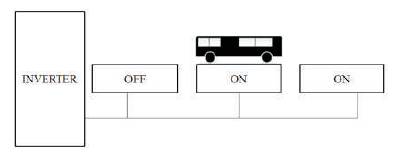
Figure 4. Concept of Power Line Segmentation Method
Simulation is well-matched for educational purpose. It is an effective way for designer to study how a circuit and its control are working. It is much inexpensive to do a thorough analysis than to build the actual circuit in which module stresses are measured. A simulation can determine the possible problems and control optimal factors, increasing the possibility of getting the prototype. New circuit concepts and parameter variations are easily tested.
Destructive tests that cannot be done in the lab, either because of safety or because of cost involved, can easily be simulated. Response to faults and abnormal conditions can also be thoroughly analyzed. The software tools are used for the simulation studies in MATLAB/Sim power systems. The MATLAB version used here is 11.0.
SimPower Systems was designed to deliver a new scheme device that permits engineers and scientists to promptly and simply build models that simulate power systems. SimPower Systems used for the Simulink location, tolerate to building a model consuming simple drag and click techniques. Analysis of the circuit contains its interface with mechanical, thermal, control, and further corrections. This is possible because all the electrical portions of the simulation cooperate with the extensive Simulink modeling library. Since Simulink uses MATLAB as its computational engine, inventors can also use MATLAB toolboxes and Simulink block sets. Figure 5 represents a power circuit for inverter system.

Figure 5. Power Circuit for Inverter System
Normally, the inverter converts the direct current into the alternating current. High frequency power inverter adapts low incidence efficacy control to high occurrence of AC control. Identical systems must be accomplished of adaptively altering the impedance of the system. Input impedance realized by the basis has to be kept at coordinated disorder underneath lively vicissitudes in WPT scheme.
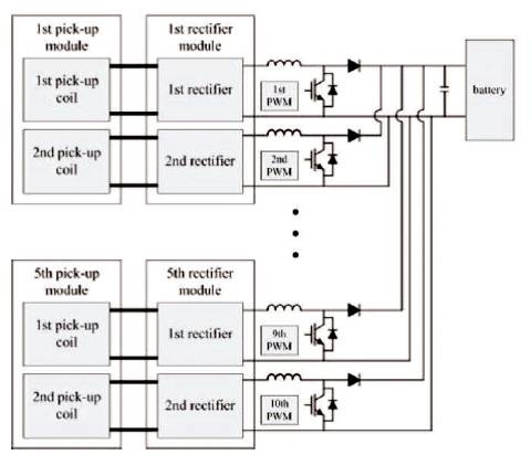
Figure 6. Functional Diagram of OLEV Power Receiver System
Figure 6 represents OLEV power receiver system. A WPT scheme contains of a power transmitter and receiver. The power transmitter consists of inverter and power lines. The power receiver contains pickup units, rectifiers, and regulators. The spontaneous modules make power from persuaded electrical energy and the rectifiers convert AC power to DC and the regulators control the output voltage, which is input to batteries and motors.
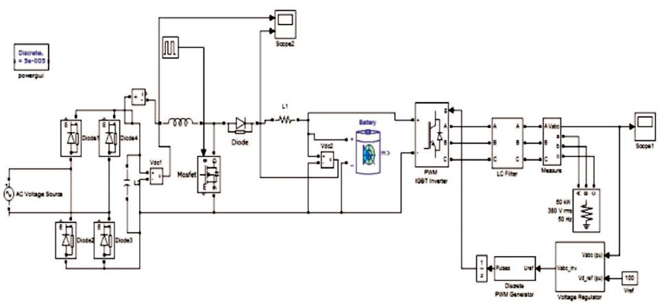
Figure 7. Simulation Model for OLEV System
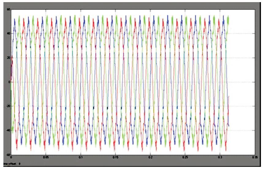
Figure 8. Simulation Results for Three Phase Sinusoidal Model
Figure 7 represents a simulation model of OLEV. The simulation model diagram was drawn using the matlab software. The various necessary components are available in the real time software. This software is used for various type of engineering fields. Mostly this type of software is used for circuit branch type of research works. Figure 8 represents simulation results for three phase sinusoidal model.
This diagram was drawn using various available components of matlab software. After drawing the diagram, we get simulated waveform of the circuit.
The design and implementation of a Wireless Power Transfer system for moving electric vehicles has been presented. A Wireless Power Transfer system uses inductive coupling. One of the most important factors that must be considered in designing an inductive coupling system is the target power of the system. To achieve high output power and power transfer efficiency, an inverter, power line modules, pickup modules, rectifiers, and regulators are optimally designed. The power supply of the proposed system consists of three phase inverter and IGBT arm. A power line segmentation method and the entire system simulation results are proposed.
In future investigations, the author would attempt to implement hardware description of the project. The hardware system will design with 80% power transfer efficiency at 26-cm air gap.