Image Denoising is a method of removal or reduction of noises, that are incurred during the image capturing, image acquisition, and transmission due to the electronic and photometric sources. This paper is mainly focused to design an efficient architecture for removal of random-valued impulse noise from corrupted images. To achieve this, a good image denoising method property is that, it will remove noise while preserving edges is proposed. The proposed methodology is Decision-Tree- Based Denoising Method (DTBDM), which consists of decision tree based impulse detector, to detect the noisy pixel and to locate the edges by an edge preserving filter to reconstruct the intensity values of noisy pixels. Further, it is enhanced by using modified square root Carry Select Adder (SQRT CSA), in order to improve the execution time. Here, the serial adder is replaced with modified square root CSA to reduce computational time and area. So this technique can be used for many real time applications like medical imaging, scanning techniques, face recognition, etc.
Nowadays the image processing is playing a vitalrole in so many applications, such as in medical applications, printing and scanning, programming, secret data communication, etc. Mean while, the images are infected with noises on the process of transmission and reception. The effected noise might fade out the image efficiency [4]. Hence here it must require an efficient restoration technique [3]. At present, in many practical applications, it is required to the use a good denoising techniques [1]-[8]. For this, a low complexity denoising [1], and enhancement techniques are essential and suitable for many VLSI architectures. This paper mainly concentrates on low complexity denoising technique for ease of implementation.
This method usually increases the global contrast of many images, especially when the usable data of the image is represented by close contrast values. Through this adjustment, the intensities can be better distributed on the histogram. So many methods are used to reduce the noise by using decision tree, but only some can reduce efficiently. In general, images are frequently corrupted by impulse noise in the events of image acquisition and broadcast.
The efficiency of the Image processing techniques mainly depends on the noise in the images. Hence, a competent denoising technique becomes a very important issue in image processing [1],[2].
In many of the applications, the image denoising is the basic technique for upcoming image processing operations, like image segmentation, image enhancement, edge detection and processing [5], object extraction, etc.
The main purpose to remove the noise is to reduce the noise by protecting image information. For this, many different techniques are proposed for reducing the impulse noise. The goal of noise removal is to suppress the noise while preserving image details. The median filter [2] , one of famous techniques, can restrain the noise. Median filter is used to change the neighborhood pixels value with median value. By this it can also change the image details, resulting in a blurred image. In order to overcome the drawback in median filter and for increments in terms of efficiency, the weighted median filter and the centerweighted median filter [4] were proposed. Even though the above two filters can also preserve more image details than median filter, they are still implemented uniformly across the image without considering whether the current pixel is noise-free or not.
The rest of this paper is organized as follows: The detailed description and types of noises are entitled in section 1, Denoising techniques and their classification in section 2. The proposed DTBDM introduced briefly in section 3. Section 4 describes the proposed VLSI architecture in detail. Section 5 illustrates the results & comparisons. The conclusion is provided in section 6, and references in section 7.
Impulse noise is one of the different categories of noise, which has unwanted spikes and continuous pops. These noises are generally created by the effect of electromagnetic interference, effect of scratch on disks, and mismatches in digital communications. The high levels of noises are harmful to the internal human organs, where even a 180 dBs is enough to damage human ears. In order to improve the robustness in adaptive machineries, an impulse noise filter is necessary to improve noise signal quality. For achieving this, a typical filter named as median is used to delete impulse noise. In order to get better performing impulse noise filters, to use model-based systems that know the properties of the noise and source signal (in time or frequency), in order to remove only impulse obliterated samples.
The impulse noise is generated based on incorrect placement of pixels from sensors, hardware collisions, or using faulty transmitting channel.
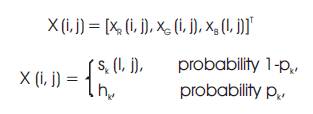
In this project, the digital color image is taken with interference of random valued impulse noise for transmission. There are three components named as R, G, B used for representing color image signal. The intersecting equation of image signal X (i, j) and effected random valued impulse noise is shown in below:
Where k is represented as R, G, B. The kth component sk (i, j) is having 256 level values, which is a 8-bit binary value and the noise probability is represented as pk (i, j). Here the noisy pixel value hk , has the range between 0 to 255 with uniform distribution. This method of signal propagation is very famous and concentrated on transmitting bit errors. Though these three components are absolutely transmitting, no correlation with random valued impulse noise occurs.
Image Denoising has remained a fundamental problem in the field of image processing. Various denoising techniques have been proposed so far and their application depends upon the type of image and noise present in the image. Image denoising is classified into two categories.
This is the traditional way to remove noise from the digital images to employ the spatial filters. Spatial domain filtering is further classified into linear filters and non-linear filters.
A mean filter is the optimal linear for Gaussian noise in the sense of mean square error. Linear filters tend to blur sharp edges, destroy lines and other fine details of image. It includes Mean filter and Wiener filter.
With the non-linear filter, noise is removed without any attempts to explicitly identify it. Spatial filters employ a low pass filtering on the group of pixels with the assumption that noise occupies the higher region of frequency spectrum. Generally, spatial filters remove the noise to reasonable extent, but at the cost of blurring the images which in turn makes the edges in the picture invisible. It includes median and weighted median filter.
The transform domain filtering is subdivided into data adaptive and non-adaptive filters. Transform domain mainly includes wavelet based filtering techniques.
Due to properties like sparsity and multi resolution structures, Wavelet transform have become an attractive and efficient tool in image denoising. With Wavelet Transform gaining popularity in the last two decades various algorithms for denoising in Wavelet Domain were introduced.
In this paper, the random valued impulse noise is mainly used with uniform distribution has been shown in [8], [9], [10], [11]. Here, the 3×3 mask is used for de-noising an image. The de-noised pixels can be placed at the coordinates (i,j) and it is displayed as pI,j . and having luminance value represented as fI,j shown in below figure Figure 1.

Figure 1. 3×3 Mask-centered on pi.j
From the input sequence of image denoising process, the other eight pixel values of input image signal, are divided into two forms: named as WTopHalf and WBottomHalf . They are represented as,


DTBDM is having two basic elements. Those are:
In order to perform correlation between pixels p and its i,j neighboring pixels, the detector can able to know whether it is noisy or not. Figure 2 Illustrates the overall flow of image denoising. If the result is positive, then only the edge preserving image filter based on direction-oriented filter generates the reconstructed value. Otherwise, it keeps the value would be unchanged.

Figure 2. Dataflow of DTBDM
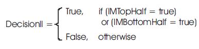
In order to determine whether it is a noisy pixel or not, have to perform the correlations between pI,j and its neighboring pixels. Surveying these methods, can simply classify them into several ways; observing the degree of isolation at current pixel, determining whether the current pixel is on a fringe or comparing the similarities between current pixel and its neighboring pixels. For this reason, in our decision-tree-based impulse detector, we have designed three modules. Those are Isolation Module (IM), Fringe Module (FM), and Similarity Module (SM) respectively. Three concatenating decisions of these modules are used to build a decision tree. The decision tree is a binary tree and determines the status of pI,j by the use of different equations in different modules. First of all we have to use an isolation module to decide whether the pixel value is in a smooth region or not.
If there is a negative response, we have to conclude that the current pixel to noisy free. Otherwise, if there is a positive response, it defines that the current pixel may be a noisy pixel or just placed on an edge. The result is confirmed by the use of fringe module in the block. If the current pixel is placed on an edge, the result of fringe module would be negative (noisy free); otherwise, the result would be positive. If isolation module and fringe module could not determine whether current pixel is noisy free or noisy pixel, we have to use another module named as similarity module to produce the result. It compares the similarity between both current pixel and its neighboring pixels. If the result is positive, pi,j is a noisy pixel; otherwise, it could be a noise free pixel. The following sections are used to describe the three modules in detailed.
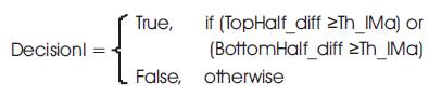
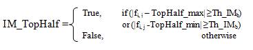
The pixels with shadow suffering from noise have low similarity compared to the neighboring pixels and socalled as an isolation point. The difference between noisy pixel and its neighboring pixel value is large. According to the above concepts, first we have to find the maximum and minimum luminance values in WTopHalf , which is named as TopHalf_max and TopHalf_min, and then calculate the difference between them, it was named as TopHalf_diff. For WBottomHalf , we have to apply the same process to obtain BottomHalf_diff. The resulting two difference values are compared with a threshold value Th_IMa to find out whether the surrounding region belongs to a smooth area or not. The equations would be generated as follows:


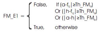
It is difficult to find out whether the pixel is noisy or situated on an edge. In order to generate the result with this case, we have to define four directions as from E1 to E4, as shown in figure Figure 3.

Figure 3. Four Directional Difference of Mask
We have to take direction E1 as an example in the above. In order to calculate the absolute difference between fi,j and the other two pixel values along the same direction, respectively, we have to determine whether there is an edge or not. The detailed equations are shown as follows.


This is the last module in the block diagram. The luminance values in the mask W are located in a noisyfree area might be close. The median value is always located at the center of the variation series, while the impulse is usually located at one of its near ends of the pixel matrix. Hence, if there are extremely big or small values, then there is the possibility to production of noisy signals. According to consideration of this concept, we have moved to sort nine values in ascending order and take the fourth, fifth, and sixth values which are close to the median in mask W. The fourth, fifth, and sixth values are represented as 4th in Wi,j , Maxi,j and Mini,j as
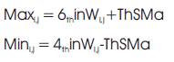
In order to show the status of pixel pi,j , Maxi,j and Mini,j are used and for more concurrent decision making, it requires changes.


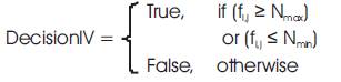
At lastly it have been concluded that pi,j is noisy pixel with respect to position of fi,j is not in between Nmax and Nmin . The edge preserving image filter will not have been supposed to construct the repeated value. Here the output value is fi,j and the equation would be,
Obviously, the threshold affects the quality of de-noised images of the proposed method. A more appropriate threshold contributes to achieve a better detection result. However, it is not easy to derive an optimal threshold through analytic formulation. The fixed values of thresholds make our algorithm simple and suitable for hardware implementation. According to extensive experimental results, the thresholds Th IMa , TH IMb , Th FMa , Th FMb , Th SMa , and Th2 SMb are all predefined values and set as 20, 25, 40, 80, 15, and 60, respectively.
To locate the edge existing in the current W, a simple edge preserving technique which can be realized easily with VLSI circuit is adopted. Only those composed of noisefree pixels are taken into account to avoid possible misdetection. Directions passing through the suspected pixels are discarded to reduce misdetection. Therefore, we use Maxi,j and Mini,j , defined in similarity module, to determine whether the values of d, e, f, g, and h are likely corrupted, respectively. If the pixel is likely being corrupted by noise, we don't consider the direction including the suspected pixel. In the second block, if d, e, f, g, and h are all suspected to be noisy pixels, and no edge can be processed, so fi,j estimated value of pi,j is equal to the weighted average of luminance values of three previously denoised pixels and calculated as (a+ b× 2+ c)/2. In other conditions, the edge filter calculates the directional differences of the chosen directions and locates the smallest one Dmin among them in the third block. The equations are as follows:

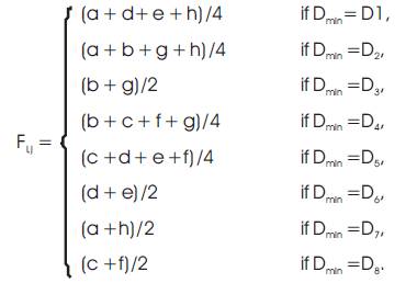
As studied in the module of Figure 4, the closest special relationship with pixel properties pi,j produced proper edge in the direction of it.

Figure 4. Eight Directional Differences of DTBDM
Here the luminance values with mean of pixels generates the directional difference as fi,j . Whenever the difference fi,j gives correct edge, then it could be located at median b, d, e, and g. If it shows wrong edge, then the median values are written in the place of difference value fi,j . It can showed in equation as,

The DTBDM is taking only two line buffers for all images to generate low latency in computation and reduces the cost of the system in VLSI platform. In order to improve timing property, the pipelined architecture is introduced with clock.
In Figure 5, comparator CMPL is used to compare two input signals and separate the large value. Like that the comparator CMPS generates small value. The first twolevel comparators are used to generate TopHalf_max and TopHalf_min. After that the result is fed to the SUB unit for perform the subtraction operation in between them.

Figure 5. Architecture of IM
The |SUB| block is used to produces absolute value from difference. The block GC further compares the two outputs from previous comparators and results the output 1 if and only if the upper value is greater than the lower value. Then OR gate produces binary value for IM_TopHalf. Finally, the multiplexer confirm the result and put out Decision II is positive. It resulting the pixel pi,j would have noise. The next module (FM) will be used to confirm the result.
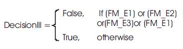
The Fringe Module (FM) is the combination of four modules named as FM 1, FM 2, FM 3, and FM 4, and each of them is used to determine its directions. The below block diagram (Figures 6 and 7) shows the detailed explanation of it. Here E1 shows direction of pixel values. The three |SUB| units are used to list out the resulting differences between the blocks.

Figure 6. Architecture of FM

Figure 7. Architecture of FM 1 module
Assuming that, if ISOLATION MODULE (IM) and FRINDGE MODULE (FM) cannot determine the noise free value or not in fi.j , in that situation the SIMILARITY MODULE (SM) is required to produces the output. The architecture of SM as depicted in Figure 8 is built with a mask w as fourth value for accelerating speed of sorting. The complete process of operation of module M0 is described as… whenever the value of a is greater than b, then C01 is going to high (1) otherwise it will be low (0). The eight number of GC values are defined as from C01 to C08.

Figure 8. Architecture of SM
The combine unit is used to combine the resulting comparing values from every comparator to generate numbers between 0 and 8. These numbers are used to specify the values order in mask W.
For suppose the value of a is small in mask W, then the output is written as 0 in mask M0 and when the value of a is biggest in mask W, then the out will be 8. Likewise the values are written for remaining outputs with only slighter difference. By the use of above method, the order of GC is developed and the result of fringe module E1 is produced by NOR gate. If the result is positive, we consider that fi,j is on the edge E1 and regards it as noise free.
The Edge Preserving Image Filter [12] is composed of two major blocks: one is minED Generator block, and another one is Average Generator block. The minED generator can generate edge values, which have minuend change. These changes are measured by using four ADD, twelve |SUB|, and four numbers of shifter blocks. Here the minuend value is calculated with Min Tree unit and it was formed by comparator series. The second block Average Generator produces pixel luminance values based on simple directional difference function (Dmin ). According to the above said, pi,j-1 , pi,j+1 , pi+1,j- 1 , pi+1,j and pi+1,j+1 pixel positions are having noise then only the multiplexer unit produces an output as (a+b×2+c)/4. Otherwise, it generates an output based on its mean value using the function Dmin . Some directional differences are determined according to four pixel values, so its reconstructive values also need four pixel values.
The general 'carry Select Adder' [12] is having a multiplexer and two ripple carry adders. In that, two ripple carry adders are used to add the two inputs having bit length 'n'.
Therefore the addition is performed twice by the use of two ripple carry adders, one time with carry high and another time carry is low. Finally, the multiplexer in the block generates the resulting output with sum and carry bits with reference to the carry bit applied at input. The Modified CSLA architecture has been developed using Binary to Excess -1 converter (BEC) [13]. This paper proposes an efficient method which replaces a BEC using common Boolean logic. The result analysis shows that the proposed architecture achieves the three folded advantages in terms of area, delay, and power.
The parallel RCA with Cin=1(high) is replaced with BEC.
To replace the n-bit RCA, an n+1bit BEC is required. Figure 9 illustrates how the basic function of the modified square root CSLA is obtained by using the 4-bit BEC together with the mux. One input of the 8:4 mux gets as it input (B3, B2, B1, and B0), and another input of the mux is the BEC output. This produces the two possible partial results in parallel and the mux is used to select either the BEC output or the direct inputs according to the control signal Cin .

Figure 9 (a) Regular 16-bit SQRT CSLA (b) Block Diagram of 16-bit Modified Square Root Carry Select Adder
The main idea is to use BEC instead of the RCA with Cin=1, in order to reduce the area and power consumption of the regular CSLA. The block diagram of 4-bit BEC is shown in Figure 10.

Figure 10. 4-bit BEC Logic Diagram
The importance of the BEC logic stems from the large silicon area reduction when the CSLA with large number of bits are designed. The Boolean expressions of the 4-bit BEC is listed as (note the functional symbols NOT, AND, XOR).
X0=∼B0;
X1=B0^B1;
X2=B2^(B0&B1);
X3=B3^(B0&B1&B2)
The characteristics and performance of the denoising method is verified by taking lena image as the test image. Consider the test image lena and by applying varying impulse noise in MATLAB Environment. The digital grey scale image taken here, cannot process in VLSI directly. So, the image is converted to its corresponding pixel values (text format), and is fed to the denoising process. The proposed decision tree based impulse detector and edge preserving filter based de-noising method in VLSI is designed using VHDL. MODELSIM is used for the simulation. Here the Peak Signal-to-Noise Ratio (PSNR) illustrating the quantitative quality of restored images of various methods is employed. The simulation result is shown in Figures 11, 12 &13.
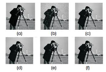
Figure 11. Results of Different Methods in Restoring 5 Percent Corrupted Image "cameraman", (a) Original Image, (b) Noisy Image, (c) Proposed, (d) Median, (e) Weighted Median, (f) Rank Order
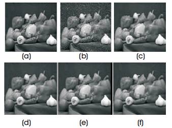
Figure 12. Results of Different Methods in Restoring 5 Percent Corrupted Image "peppers”, (a) Original Image, (b) Noisy Image, (c) Proposed, (d) Median, (e) Weighted Median, (f) Rank Order

Figure 13. Results of Different Methods in Restoring 5 Percent Corrupted Image "Lena", (a) Original Image, (b) Noisy Image, (c) Proposed, (d) Median, (e) Weighted Median, (f) Rank Order
The final waveform is generated in MODELSIM after simulation of proposed DTBDM is shown in Figure 14.

Figure 14. Simulation Waveform of DTBDM
The Synthesis report generated using XILINX ISE suit, for both serial adder and 16-bit modified square root CSA of area and time comparison is tabulated in Table 1.

Table 1. Comparison Results
The authors employ the Peak Signal-to-Noise Ratio (PSNR) to illustrate the quantitative quality of the reconstructed images for various methods. Table 2 lists the restoration results in PSNR (dB) of test images corrupted by 5 percent impulses, respectively. Generally, the cost of VLSI implementation depends mainly on the required memory and computational complexity. The proposed design requires only few computations. In [11], the author claims that their method achieves better filtering quality with lower complexity than other methods. Therefore, we can conclude that the DTBDM outperforms other methods [7], [8], [9] , [10] in terms of quantitative evaluation.

Table 2. Comparative Results in PSNR (dB) of Images Corrupted by 5 Percent Impulses
A VLSI architecture for efficient removal of impulse noise and image enhancement is proposed. The approach uses an decision tree based image detector to detect the noisy pixels and edge preserving filter to locate the edge. By this adaptive design, the quality of the reconstructed image is improved noticeably. The experimental results demonstrate that the performance of the proposed technique is superior to the lower complexity methods, i.e., Median, Weighted median, Rank order filter, in terms of Peak Signal-to-Noise Ratio (PSNR) both quantitative evaluation and visual aspect. Additionally, by using the modified square root Carry Select Adder, the execution time and area is reduced. Hence in many real time applications, this proposed system can be applicable for color images and can consider different types of noises for further study.