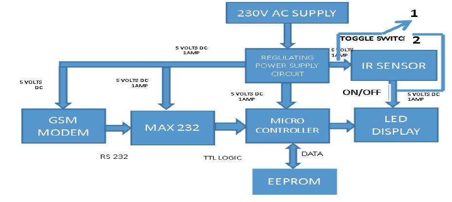
Figure1. Block Diagram of the Proposed Model
Information display system proposed in this paper is an efficient, wireless and smart mode of communication in public places. Public announcement system, programmable sign boards, notices in hard copy form, etc are hardwired, complex in nature, requires manpower and have some time-delay. All these limitations are overcome by the proposed model. This paper describes an advanced notice board that can be operated with GSM technology or with a PC with an administrator. It is GSM based that displays information upon receiving SMS from an authorized user. Use of GSM technology for communication enables the remote operation. The LED board can also be connected to a PC, to display the message. This work is done by designing and integrating the hardware and software with a microcontroller, GSM module, PIR sensor, and a LED display.
In today's world of technology, communication and management is necessary in any part of the world. People from different parts of the globe are ready to communicate with one another within fraction of seconds. GSM communication (Global System for Mobile Communication) is the most widely used wireless communication networks for calling and sending SMS (Short Message Service). It is aimed at the colleges and universities for displaying day-to-day information continuously or at regular intervals during the working hours. Being GSM-based, the system offers flexibility to display flash news or announcements faster than the programmable system as done in [1]. In [2], ATMEL89S51 microcontroller is used and in [3], ATMEGA32 has been programmed. In [4], the results were verified in 8051 simulator.
In this paper, digital notice board based on GSM technology is used to display the notice on a LED Display. Whenever any information is to be displayed, the user sends it from an authorized mobile number in the defined message format. GSM MODEM connected to the LED Display receives the SMS. The microcontroller reads the message form serial port and verifies for the password. If the password is correct, then the message is scrolled on the LED display. With the help of a PIR sensor, the LED display is operated by ON/OFF technique with the detection of human activity, thereby conserving energy. A manually operated-toggle switch is provided to bypass the PIR sensor, in case the message must be scrolled continuously.
The system mainly consists of a GSM receiver and a LED display. They can be programmed from an authorized mobile phone. It receives the SMS, validates the sending Mobile Identification Number (MIN) and displays the desired information after necessary code conversion. It can serve as an electronic notice board and displays the important notices instantaneously, thus avoiding the latency. Being wireless, it is easy to expand and allows the user to add more display units at any time and at any location, depending on the requirement of the user. When it is required to display any information, the user sends the message from the authorized mobile in the desired format.
The message is sent through a mobile which is thereby accepted by a GSM module SIM 900. The authentication of the mobile number is done by the AT89S52 microcontroller. The microcontroller is programmed in such a way that, when the modem receives any message, it will read the message form a serial port and verifies for the password. If the password is correct, then the message is displayed on LED. The messages are stored in EEPROM so that, no previous messages are lost even after a power failure.
Several modes of operation of the developed module are:
1) GSM based, with Human Detection: In this mode, the message is sent to the microcontroller from an authorized mobile. PIR sensor is enabled. Thus, in case, no human is detected in the range of the PIR sensor, the message is not displayed.
2) PC based, with Human Detection: In this mode, the system is connected through a wire to a PC. Message is sent to the microcontroller from the PC. PIR sensor is enabled. Thus, the message is displayed only when the PIR sensor detects human activity in it's range.
3) GSM based Continuous Message Display System: It is a wireless mode of operation, wherein the message is sent to the microcontroller from an authorized mobile. PIR sensor is bypassed by closing the toggle switch across the PIR sensor to position 2, as shown in Figure 1.Thus, the message is displayed continuously, until there is power supply.
4) PC based continuous message display system : In this mode, the display system is connected through a wire to a PC. Message is sent to the microcontroller from the PC. PIR sensor is bypassed by closing the toggle switch to position 2, as shown in Figure 1. Thus, message is displayed continuously, until there is power supply.
Figure1. Block Diagram of the Proposed Model
In modes 1 and 2, LED is operated by ON/OFF technique with the detection of human activity. Sensors are prone to frequent maintenance, therefore, PIR sensor can be bypassed in case of it's maintenance using the manuallyoperated toggle switch. Reliability of the display system is ensured. This is featured in modes 3 and 4 of operation.
The overall circuit diagram is drawn with the help of Proteus software as shown in Figure 2.
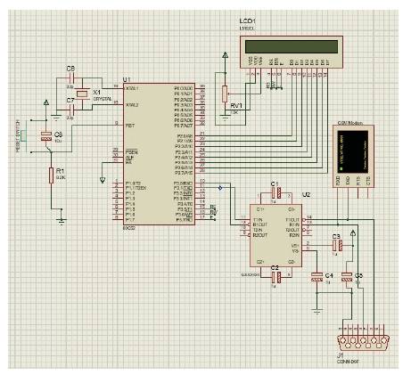
Figure 2. Overall Circuit Diagram
To know the main working of the project, the working of the components is required. They are discussed below:
The various components required in this project are:
This circuit is designed to develop the required voltage which helps to run the main circuit and it's components. With the help of the rectifier, AC supply is converted into DC. The output from the regulated power supply will be the required DC output.
A GSM Modem is a device which can be used to make a computer or any other processor communicate over a network. A GSM modem requires a SIM card to be operated and operates over a network range subscribed by the network operator.
One of the key features of GSM is the Subscriber Identity Module, commonly known as a SIM card. This SIM card is placed in the GSM modem, which contains the user subscription information.
Liquid Crystal Display commonly called as LCD is an electronic device which is used for displaying the text or any characters. Here a 14 pin LCD is used. It can display 16 characters and 2 lines. They are economical and are easily programmable and can display custom and special characters.
MAX 232 is used to interface the GSM Modem with the microcontroller, which converts the RS232 signals to TTL/CMOS Levels. A standard serial interface for PC, RS232C, requires negative logic, i.e., logic 1 is -3V to -12V and logic 0 is +3V to +12V [5]. It is a dual RS232 receiver transmitter that meets all the RS232 specifications while using only +5V power supply [6].
A microcontroller is an integrated circuit or a chip with a processor and other support devices integrated together. [7].Microcontrollers are designed for embedded applications, in contrast to the microprocessors used in personal computers or other general purpose applications consisting of various discrete chips.
A Passive Infrared Sensor (PIR) is an electronic sensor that measures infrared light radiating from objects in its field of view. The PIR sensor IC consists of 3 pin -V , Ground and cc Output. It consists of pyro electric materials which generate energy when exposed to heat [8]. When a human is detected in the range of the sensor, it converts the resulting change in the incoming infrared radiation into a change in the output voltage, and this triggers the detection, thereby reducing the consumption of energy by switching off the LED display when there is no person at the sensor.
These memory devices are used to store the data for offline processes. The AT24C64 provides 65,536 bits of serial Electrically Erasable and Programmable Read Only Memory (EEPROM) organized as 8192 words of 8 bits each. The AT24C64 is available in space saving 8-pin PDIP. The AT24C32/64 proves 32,768/65,536 bits of serial Electrically Erasable and Programmable Read Only Memory (EEPROM) organized as 4096/8192 words of 8 bits each.
LED is a device that emits light when electric current flows through it. LED display used here is 2 feet, 4 inch display which is based on DOT matrix. The message sent from a mobile will be displayed in this LED display. A Light Emitting Diode (LED) is essentially a PN junction diode. When carriers are injected across a forward-biased junction, it emits incoherent light. Most of the commercial LEDs are realized using a highly doped n and a p junction.
Here the DPDT toggle switch is used to bypass the sensor. In any circumstances, if the sensor fails to work, the display goes off and so to avoid that, this switch is used, where two modes are introduced [manual and auto modes].
All the hardware components are connected as shown in Figure 3.
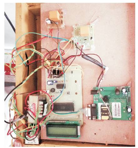
Figure 3. Power and the Control Circuit of the Model
Embedded C is a set of language extensions for the C Programming language by the C Standards committee to address commonality issues that exist between C extensions for different embedded systems [9]. Embedded C programming requires nonstandard extensions to the C language in order to support exotic features such as, fixed point arithmetic, multiple distinct memory banks, and basic I/O operations. Programs can be developed as per this electronic hardware using a microcontroller.
Keil development tools for the Microcontroller Architecture support every level of software developer, from the professional applications engineer to the student just learning about embedded software development. Keil tutorial will introduce all the basic programming techniques. It will also show about, how to use the KEIL IDE. The main difference is all about the limitations of the processor of the 89S52 microcontroller as compared to the modern computers.
When a modem is connected to any device AT commands are needed to direct the modem for its operations. Basically commands are sent directly to the modem after activating the Terminal mode. To send any SMS message, AT commands are required. Their purpose is to get the attention of the modem. The general AT commands are discussed below.
Command Format

AT: attention code.
Command : a command consisting of one letter.
Argument:Optional information that further defines the command
=n: used when setting a register.
As shown in Figure 4, message is sent as “12EE31” in the proper format. When “<” is received, the message reading starts and when “>” is received, reading of the message is terminated. Thus, the message to be displayed is kept between < and >. The message is received by the GSM module and is passed onto the microcontroller using serial communication. The GSM module uses the AT commands presented in a proper syntax. The GSM module receives the message and stores in the memory available in the SIM card. When the AT command is executed in the microcontroller, the message is transferred to the microcontroller. The GSM is connected to a microcontroller board through serial communication using RS232 cable (DB9 pins). The LED display board is connected to microcontroller board by pins directly as shown in Figure 2. Initially when the power is switched on and all the modules are kept ready, no message is sent to the GSM module. In the meanwhile, by default, date and time are scrolled on the LED. All the steps involved in the process are illustrated in Figure 4.
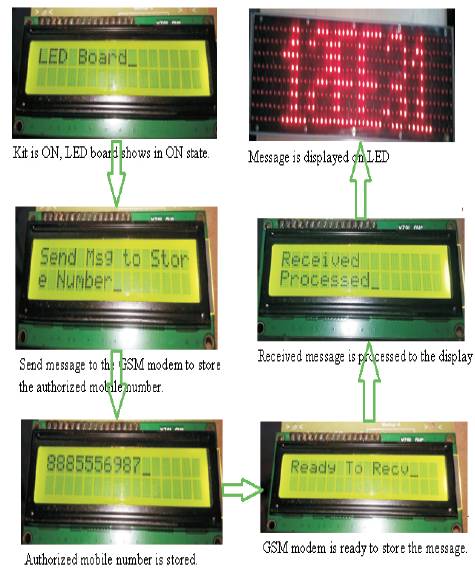
Figure 4. Implementation Sequence
GSM based information system is successfully being operated to display various notices to different groups of public at Vignan's Institute of Information Technology. It is used to inform the students about various notices and also to keep them updated about the campus news. Figure 5 illustrates the same.
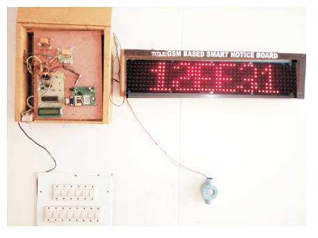
Figure 5. Real-time Implementation of the Model
With the development of the concept of wireless technology, we are able to create our communication making it more economical, faster, and with greater efficiency. We can display the messages from a remote location with fewer errors and less maintenance. The manually- operated toggle switch is the major highlight of the model. This ensures reliability of the display system even in case of failure of the PIR sensor. This work helps to gain knowledge and experience in developing a real time application. Security can be enhanced and awareness of the emergency situations may be created using this information system.