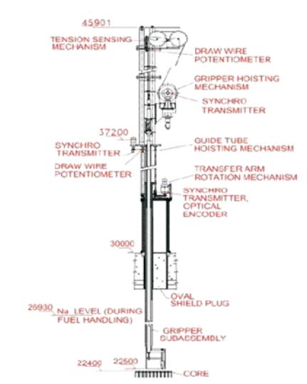
Figure 1. Structure of the Transfer Arm
Transfer Arm (TA) is an offset arm type fuel-handling machine which is designed to handle core sub-assemblies consisting of fuel, absorber, blanket and reflector sub assemblies. The Transfer Arm Examination Facility (TAEF) control system is to facilitate the operation of Transfer Arm from the local control panel. The control system controls the raising and lowering of Guide Tube, raising and lowering of Gripper Hoist, rotation of Top Structure, opening and closing of Gripper Fingers and locking and unlocking of gripper hoist. The embedded control system has to be highly reliable as it will affect the safety and availability of nuclear plant. Hence, it is proposed to develop a real time embedded control system to carry out the safe operations on Transfer Arm. The project work involves, modelling the control logics (interlocks) using Safety Critical Application Development Environment (SCADE) suite, carryout the model coverage and simulation analysis and formal verification of the model using design verifier of the SCADE suite by creating few critical properties. The SCADE generated code has to be integrated with the hardware using cross complier, generate executable file and test the functionality system. The manual code shall contain necessary diagnostic logics to test the healthiness of the system. Adequate test cases have to be generated from the requirements. The status of all drives will be monitored through a GUI.
Prototype Fast Breeder Reactor, a 500 MW, sodium cooled fast breeder reactor is in advanced stage of construction in Kalpakkam. Transfer Arm is an offset type fuel handling machine used to replace the fuel inside the fast breeder reactor periodically. The operation of this machine is called only when the reactor is in shutdown state. The lower portion of the Transfer Arm is exposed to cover gas and sodium in reactor during fuel handling and reactor operation. For doing any maintenance in lower part, Transfer Arm is brought under decontamination facility for sodium cleaning. After cleaning it is brought to Examination Facility in Reactor Containment Building to do maintenance work on this Transfer Arm. The function of TAEF control system is to check the safe operation of Transfer Arm in TAEF.
The TAEF-RTC is to facilitate safe and reliable operation of the Transfer Arm from Local Control Panel. This control system ensures whether operation is executed only when all the necessary conditions are satisfied. TAEF-RTC will receive field signals from Transfer Arm, control the commands from Local Control Panel, process them and initiate control action of the mechanism. In addition, this system sends the processed data and alarm messages to the local display station. The TAEF-RTC is dedicated for Transfer Arm operation only and no other operation is controlled by RTC.
Transfer Arm consists of four drives Guide Tube, Gripper Hoist, Gripper Finger and Top Structure. The structure of the Transfer Arm is shown in the Figure 1.
Figure 1. Structure of the Transfer Arm
All the drives employed in Transfer Arm need to be operated on mutually exclusive basis. This is achieved by using drive selector switch. There are four positions on the switch corresponding to the four drives. At a time, the drive selector switch can positioned on any one position only. Hence one of the four drives can be selected at any time. In order to execute any operation that is issued by the operator, the particular drive is selected first whose service is needed. Then using drive selector switch and mode selector of the drive being operated, the desired operation is executed (eg: raise / lower) on the particular drive. Based on the selection of drive and mode selector switches from the Local Control Panel, 19 control commands are given to Transfer Arm from the Motor Control Panel. The control commands includes operations in Transfer Arm such as,
The function of the control system is to check the smooth and safe operation of Transfer Arm in TAEF. The context diagram of TAEF-RTC is shown Figure 2. The control system ensures that, any operation is executed when all the necessary conditions are satisfied. The programmable real time computer permits all the operations to be performed on Transfer Arm and display/indicate the status/position of all the drive mechanism. The TAEF control system has to scan nearly 103 digital inputs, 7 analog inputs, 3 synchro inputs and one optical encoder input. The system has to give 55 potential free contact outputs to drive the four drive mechanisms of Transfer Arm and the indication lamps at Local Control Panel. Also three analog outputs are used to drive the Guide tube, Gripper Hoist and Top Structure through VFD control. TAEFRTC contain CPU card, analog input card, digital input card, synchro to digital converter card, encoder interface card, analog output card and digital output card. All the signals are connected to the system to do the processing as per the control logic and send the outputs to the Transfer Arm and Display Station through Ethernet. When the system fails, fail safe outputs can be routed to the plant.
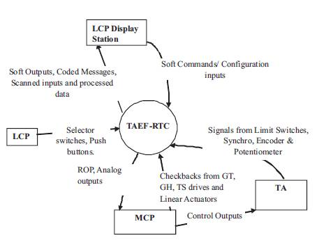
Figure 2. Context Diagram of TAEF-RTC
Transfer Arm Examination Facility Control system has to highly reliable since it will affect the safety of the nuclear power plant. SCADE (Safety Critical Applications Development Environment) tool is used to develop the embedded software for critical applications through modelling. SCADE is used to create detailed design specification that completely models the functional behaviour of the system. This high-level design model documents the specification of the designer that it provides both simulation and formal verification of the design model.
The behaviour of the system can be modelled as state based approach or data-flow model. The top level of the TAEF-RTC is modelled on the basis of state model.
Each drives in the Transfer Arm is represented as states. There will be switch between the drives based on the selection of drive switches and condition for the operation of each drives. Then the modes involved in each drives are modelled using data-flow model as shown in Figure 3.
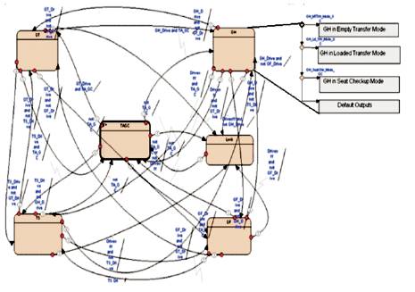
Figure 3. SCADE Model for TAEF-RTC
The operations involved in each drives is modelled as operators. The SCADE model for Gripper Finger is shown in Figure 4. TAEF-RTC model has 28 operators which includes model for the condition for operation of each drives and operations involved in it. In this model, the sensor inputs include outputs from the limit switches, selector switches, push buttons and sensors like synchro and potentiometer. KCG code generator will generate C code for model comply with MISRA C guidelines.
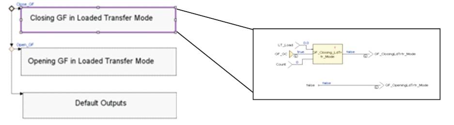
Figure 4. SCADE Model for Gripper Finger
SCADE tool provides Model Test Coverage analysis. SCADE suite Model Test Coverage is a coverage analysis tool that executes and reports on requirements-based test coverage for SCADE suite models. MTC tracks successful execution paths and percentage of each SCADE suite operator is tested and enables MC/DC (Modified Condition/Decision Coverage) analysis at the SCADE suite model level.
This paper proposed a model based approach for the development of Real Time Control system using SCADE tool. Model Test Coverage is SCADE tool simplifies the verification of critical application design and automating the generation of coverage analysis report.
The SCADE suite KCG code generator provides complete traceability from model to generated code by establishing an unambiguous one to one relationship between the model and the code.
The proposed system uses SCADE tool to generate the programming logic for the operation of TAEF. Further the Hardware programming can be implemented in TA by using the 'C' so that it can be tested in real time.