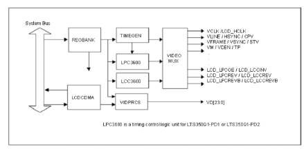
Figure 1. LCD Controller Block Diagram[1]
Based on the idea of combining Embedded system with Image processing, this paper designs an embedded system which simulates the weapon mode. In this a background picture should be moved quickly by S3C2440 processor which is based on ARM9.Due to the limitation of hardware resources in embedded systems, it is difficult to realize high speed image processing with conventional solution. In this paper, the authors discussed about the DMA technology and Software Algorithm that provides smooth, stable and fast moving images. It provides good reference for graphic development on embedded systems.
In order to achieve simulation of some weapons system , a computer is used to control keys and output scene which should be shown on the weapons system. We choose the S3C2440 RISC microprocessor which is based on ARM9 architecture and produced by Samsung Corporation, to satisfy the reliability and portability of the system. When the scenes change quickly it is very difficult to show it clearly, because of the hardware limitations of embedded system resources.
The LCDCDMA is a dedicated Direct Memory Access (DMA), which can transfer the video data in the frame memory to LCD driver automatically. [2], [12] Using this special DMA, the video data can be displayed on the screen without CPU intervention.
The VIDPRCS receives the video data from LCDCDMA and sends the video data through CD[23:0] data ports to the LCD driver after changing them into suitable data format. (For example: 4/8 -bit single scan or 4 bit single scan display)
The TIMEGEN consists of programmable logic that supports the variable requirement of interface timing and rates that are commonly found in different LCD drivers. The S3C2440A supports four-channel DMA controller located between the system bus and the peripheral bus. [1] Each channel of DMA controller can perform data movements between devices in the system bus and/or peripheral bus with no restrictions. The operation of DMA can be initiated by software, or requests from internal peripherals or external request pins. DMA uses three-state FSM (Finite State Machine) for its operation, which is described in the following three steps:
The S3C2440A is developed with ARM920T core, 0.13um CMOS standard cells and a memory complier. Its lowpower, simple, elegant and fully static design is particularly suitable for cost- and power-sensitive applications. It adopts a new bus architecture known as Advanced Micro controller Bus Architecture (AMBA).
The S3C2440A offers outstanding features with its CPU core, a 16/32-bit ARM920T RISC processor designed by Advanced RISC Machines, Ltd. The ARM920T implements MMU, AMBA BUS, and Harvard cache architecture with separate 16KB instruction and 16KB data caches, each with an 8-word line length by providing a complete set of common system peripherals. The S3C2440A minimizes overall system costs and eliminates the need to configure additional components.
S3C2440 has a LCD controller (Figure 1) which consists of the logic for transfering LCD image[6] data from a video buffer located in system memory to an external LCD driver. It is easy to implement output on S3C2440 by the LCD controller. The S3C2440 LCD controller is used to transfer the video data and to generate the necessary control signals[3], such as VFRAME, VLINE, VCLK, VM and so on. In addition to the control signals, S3C2440A has the data port for video data ,which are VD[23:0]. The LCD controller consist of REGBANK, LCDCDMA, VIDPRCS, TIMEGEN and LPC3600. The REGBANK has 17 programmable register sets and 25×16 palette memory which are used to configure the LCD controller. TIMEGEN block generates VFRAME,VLINE,VCLK,VM, and so on. The LCD controller in the S3C2440A consists of the logic for transferring LCD image data from a video buffer located in system memory to an external LCD driver [8, 10]. The LCD controller supports monochrome, 2-bit per pixel (4- level gray scale) or 4-bit per pixel (16-level gray scale) mode on a monochrome LCD, using a time-based dithering algorithm and Frame Rate Control (FRC) method and it can be interfaced with a color LCD panel at 8-bit per pixel (256-level color) and 12-bit per pixel (4096-level color) for interfacing with STN LCD.It can support 1-bit per pixel, 2-bit per pixel, 4-bit per pixel, and 8-bit per pixel for interfacing with the palletized TFT color LCD panel, and 16-bit per pixel and 24-bit per pixel for non-palletized truecolor display. LCD controller can be programmed to support different requirements on the screen related to the number of horizontal and vertical pixels, data line width for the data interface, interface timing, and refresh rate.
Figure 1. LCD Controller Block Diagram[1]
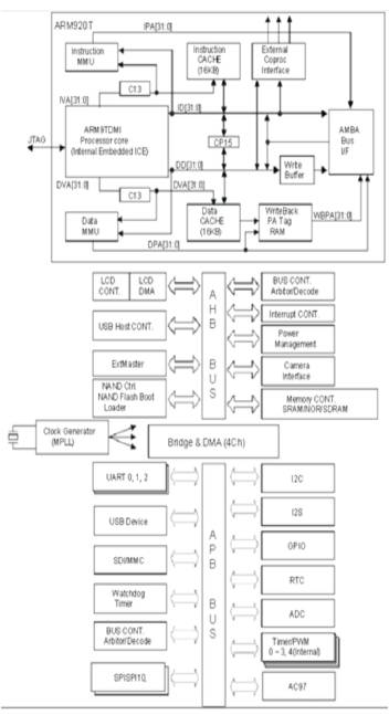
Figure 2. S3C2440 BlockDiagram[1]
FIFO memory is present in the LCDCDMA. When FIFO is empty or partially empty, the LCDCDMA requests data fetching from the frame memory based on the burst memory transfer mode (consecutive memory fetching of 4 words (16 bytes) per one burst request without allowing the bus mastership to another bus master during the bus transfer).When the transfer request is accepted by bus arbitrator in the memory controller, there will be four successive word data transfers from system memory to internal FIFO [2]. The total size of FIFO is 28 words, which consists of 12 words FIFOL and 16 words FIFOH, respectively. The S3C2440A has two FIFOs to support the dual scan display mode. In case of single scan mode, one of the FIFOs (FIFOH) can only be used.
The S3C2440A LCD controller (Figure 2) supports 8-bit color mode (256 color mode), 12-bit color mode (4096 color mode), 4 level gray scale mode, 16 level gray scale mode as well as the monochrome mode. For the gray or color mode, it is required to implement shades of gray level or color according to the time-based dithering algorithm and Frame Rate Control (FRC) method. The selection can be made following a programmable lockup table, which will be explained later. The monochrome mode bypasses these modules (FRC and lookup table) and basically serializes the data in FIFOH (and FIFOL if a dual scan display type is used) into 4-bit (or 8-bit if a 4-bit dual scan or 8-bit single scan display type is used) streams by shifting the video data to the LCD driver DMA controller is located between the system bus and peripheral bus, it can perform data movements between devices in the system bus and peripheral bus with no restrictions. And the main advantage of DMA is that it can transfer the data without CPU intervention [11], [13]. The operation of DMA can be initiated by software, or request from internal peripherals or external request pins. We need to allocate a piece of space, and set the start address and end address according to the DMA address by the LCD controller special register. [6] (Figure 3).
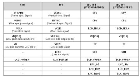
Figure 3. S3C2440 External signal interface[1]
The influence factors determining display speed are bus bandwidth,data quantity and CPU frequency.
Bus Bandwidth means the data transfer capacity, or speed of transmission, of a communications system as measured in bits per second. In computer system , bandwidth is often used as a synonym for data transfer rate, the amount of data that can be carried from one point to another in a given time period.
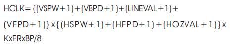
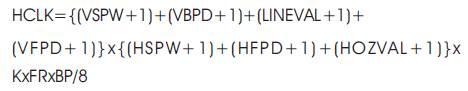
where FR is frame rate, BP is BPP,K is a parameter which is used to adjust FR. The other parameters should be set according to the particular hardware. In this, resolution is 900x700,BPP is 29. The bandwidth allocated to display equals 93.3M. System bus bandwidth is 100M.
Data quantity is another influence factor determining the display speed. It should be defined according to system requirement before hardware design. Data quantity is influenced by resolution and it is bit deep. Resolutions decide the quantity of pixels, as well as bit deep decides how many bytes consist of one pixel data.
Besides bus bandwidth and data quantity, CPU frequency is also related to display speed. To some degree, the CPU with higher frequency can process data more quickly. But CPU is incapable to deal with the limitation of bus bandwidth.
When large number data should be sent, calculate bus bandwidth for LCD in the system. The Bus bandwidth is
On the condition that no hardware changes occur, skip over device DC expending large quantity system resource and control the frame buffer directly. The scene data will be copied from system heap to frame buffer in RAM and as a result, display speed is improved greatly. An example of LCD timing is shown in Figure 4.
The upheap data with background bitmap is set to be convenient for operating data. The bitmap is converted in to an one dimensional array. Bitmap is always a file with image pixels data. The data arranged are according to the hardware requirement.
In Windows, bitmaps are used to represent graphical images. A bitmap typically contains the pixel data for the image, the dimensions and colour depth of the image, and possibly the palette for the image, among the other things. Information in Windows bitmap is not directly available, but is abstracted and only accessible through calls to Win32 APIs. A Window CE display driver typically sees bitmap, in a format called surface. These surface contain the information of bitmap ,but in a format that is directly accessible by the display driver [7].
Device–Dependent Bitmaps (DDBs) are described by using a single structure, the BITMAP structure. The members of this structure specify the width of the array that map entries from the device palette to pixel and the device's colour format, in terms of colour planes and bits per pixels. An application can retrieve the colour format of a device by calling the Get Device Caps function and specifying the appropriate constants. DDB does not contain colour values, instead the colors are in a devicedependent format. For more information, see color in Bitmaps. Because each device can have its own set of colors, a DDB created for one device may not display well on a different drive.
A Device–Independent Bitmap (DIB) contain a color table. A color table (Table 2) describes how pixel values correspond to RGB color values, which describe colors that are produced by emitting light. Thus, a DIB can achieve the proper color scheme on any device. A DIB contains following color and dimension information. The color format of the device, the resolution of the device, the palette for the device on which the image was created, an array of bits that map Red, Blue, Green(RGB) triplets to pixels in the rectangular image and a data compressor identifier that indicates the data compression scheme are used to reduce the size of array of bits (Figure 5).
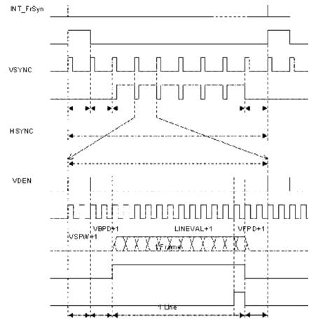
Figure 4. LCD Timing Example[1]
The colour and dimensions information is stored in a BITMAPINFO structure , which consists of a BITMAPINFOHEADER structure followed by two or more RGBQUAD structures (Table 1). The BITMAPINFOHEADER structure specifies the dimensions of the pixel rectangle, describes the device's color technology, and identifies the compression schemes used to reduce the size of the bitmaps. A Device-Independent Bitmap (DIB) is a format used to define device-independent bitmaps in various color resolutions. The main purpose of DIBs is to allow bitmaps to be moved from one device to another (hence, the device-independent part of the name). A DIB is an external format, in contrast to a device-dependent bitmap, which appears in the system as a bitmap object (created by an application...). A DIB is normally transported in metafiles (usually using the StretchDIBits() function), BMP files, and the Clipboard (CF_DIB data format).
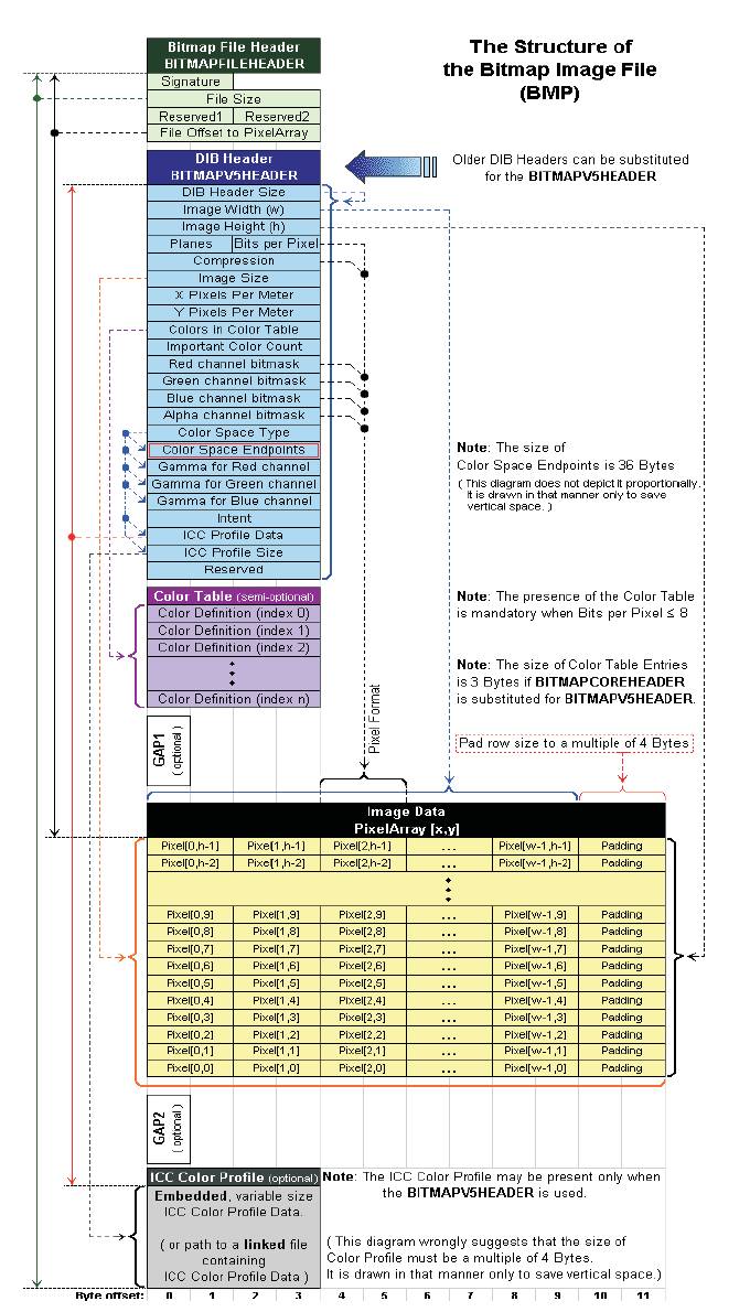
Figure 5. DIB Bit map image file[4]
When a process is created on a windows Mobile –based pocket PC, a stack is created for the thread belonging to that process. Likewise, for each new thread that is spawned in the process, a separate stack is created.
To store the values of parameters passed to functions and variables created in functions, the stack provides 58KB of usable memory. The stack memory used by a function is freed when the function returns.
One cannot create private stacks as you can with heaps, nor can increase the size of the stack. Exceeding the 58- KB stack limitation can cause a failure in the application.
Heaps:Each process started on a windows Mobile-based pocket PC creates a default heap, which cannot be deleted but is automatically freed when the application process ends. Memory is allocated and freed from the heap through any of the following means: new and delete operators in C++,malloc, calloc, realloc, and free functions in C and LocalAlloc , HeapAlloc, LocalFree, and Heapfree windows CE functions.In addition to windows CE provides two API functions to allocate and free mass memory:
LPVOIDVirtual Alloc (LPVOID ip Address, DWORD dwSize, DWORD fl Allocation Type, DWORD flprotect);
BOOL Virtual Free(LPVOID ipAddress, DWORD dwSize, DWORD fl Allocation Type, DWORD flprotect);
Whenever memory is allocated, one must check that RGBQUAD structures identify the color that appears in the pixel rectangle.
Besides, there are two varieties of DIBS: a bottom –up DIB,in which the origin lies at the lower-left corner and a top-down DIB, in which the origin lies at the upper –left corner. The output video data with following format 18bpp and 5:5:5,means that one pixel should be expressed with two bytes and three colors (red, green and blue) should be 5 bit, 5bit and 5bit.
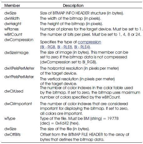
Table 1. Bitmap Info header
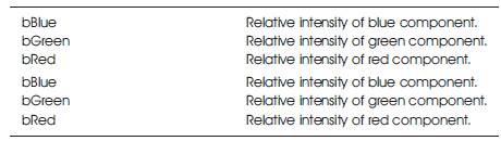
Table 2. Color Table
There are various methods for control frame buffer in various OS. Although Windows CE OS protects memory to prevent system from being modified by application unexpectedly , it provides some windows API functions to implement controlling memory freely. Through these functions we can map frame buffer address to RAM heap, and then control frame buffer freely.
There are important factors about how your applications allocate memory to manage static and global variables, stacks, and heaps.
Static and global variables are created when a process starts and cannot be freed until the process ends. Therefore, one should limit the use of static and global variables, especially with large memory allocations and arrays.
When the memory allocations are full, one can ask the shell to free additional memory by calling the SHCloseApps functions and passing the amount of memory that your applications require.
With repeated allocation and deallocation of memory, the heap becomes fragmented, causing additional requested allocation. This effect becomes more pronounced in long-running applications like those typically used on mobile device.
If application requires repeated allocations and deallocations of heap memory, you should consider using the Windows CE HeapCreate function to create a private heap in application. Private heap can be deleted to free all memory an that heap.
After all pixel data have been set up to memory, well crop a part of them and copy to frame buffer in some algorithm (Figure 6). The rectangle outside means a background bitmap, and rectangles inside show the secne which will be shown on screen and move along with view point D quickly. Address offset offgset of first pixel on some line in screen can be expressed to
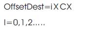
The corresponding bytes address offset in bitmap array is:
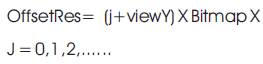
Having these two offsets, pixels data are converted into frame buffer one by one with memory copy function in double circulation.
Figure 8 shows a bitmap with some coordinates. A pixel is pictured as a square. 24 bit is the Windows internal format. In this application, the 32 bit format is used. In this format, the colors red and blue have traded positions in the 32 bit word as compared to the windows format, so red is positioned in bits 16..23 and blue in bits 0..7. If a variable "color" has to receive the data of pixel [x,y] of a bitmap named bm1 then,
color := bm1.canvas.pixels[x,y]
does the job. Note, that "color" has the Windows format, regardless of the format in which the colors were stored in the bitmap. For further extraction of the individual color intensities into bytes R,G,B , use the statements:
R := color and $ff; G := (color shr 8) and $ff; B := (color shr 16) and $ff;
To show the bitmap on the screen using a paintbox component on form1 while positioning the left-top at paintbox position [x,y] , use the statement:
form1.paintbox1.canvas.draw(x,y,bm1)
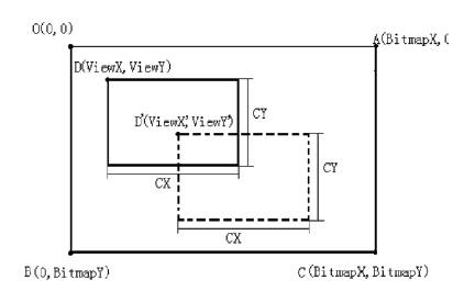
Figure 6. Display Algorithm
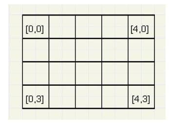
Figure 7. Pixel pictured as square
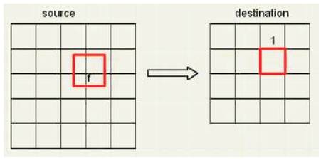
Figure 8. Reduction of picture
Figure 9 shows a source- and destination bitmap. The source bitmap has 5 rows of 5 columns, the destination is a 4 * 4 bitmap.
We regard the bitmaps as pieces of paper. A pixel is given by the dimension 1 * 1.The destination bitmap dimensions are the dimensions of the source bitmap divided by a factor f. So, for each destination pixel, a corresponding area (f*f) on the source map may be drawn. In most cases, this area will partially overlap the pixels in the source. The color of a destination pixel is the (weighted) addition of the colors of the pixels covered on the source map. In Figure 9, 4 pixels in the source contribute to the (marked) pixel in the destination This contribution is proportional to the area covered. We zoom into the picture to show the details:
We see a part of the source bitmap with 4 pixels:c
ABCD : [i,j]
DCHI : [i+1,j]
BEFC : [i,j+1]
CFGH : [i+1,j+1]
The destination-pixel [x,y] dimensions are multiplied by f and projected on the source bitmap. This projection is the (red) rectangle PQRS (Figure 10). We must clearly distinguish pixel positions in the bitmap and distances on the map. Pixel positions are [i,j] , so point A has distance i to the left and j to the top.sx1,sx2,sy1,sy2 are variables of type single, which hold therefore floating point values indicating the distance of the (red) square edges to the edges of the map. Note , that PS = PQ = sx2-sx1 = sy2-sy1 = f; Note, that destR, destG, destB have been set to 0 after advancing to a new destination [x,y]. To calculate the color of destination-pixel [x,y], the above statements must be repeated4 times, for all source pixels ABCD, DCHI, BEFC, CFGH. This concludes the description of the algorithm. For the reduction of a picture, a similar description holds. Figure 11picture of the form, showing the results.
The over all procedure is:
For larger images, the program is rather slow.
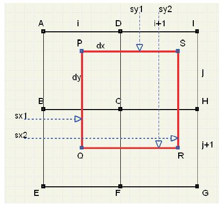
Figure 9. Bit maping
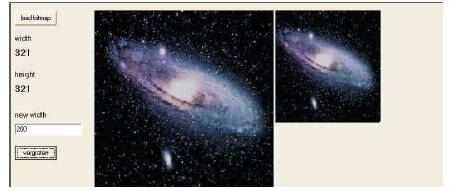
Figure 10. Reduced picture size with bitmap
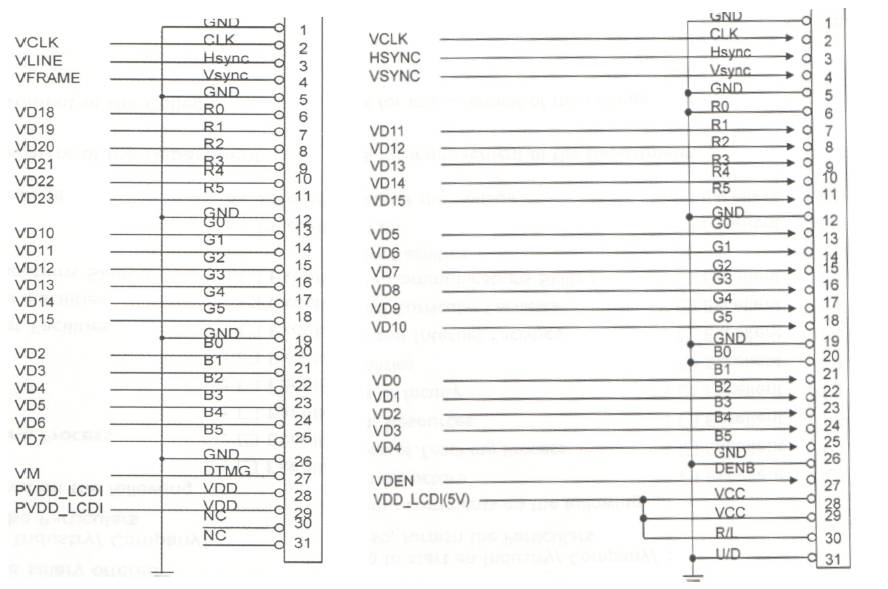
Figure 11. Interfacing of Mono STNLCD[1]
For many developers, writing display drivers can be an intimidating task. Windows CE, Microsoft's operating system targeted towards embedded devices, is no more used. The system chart is shown in Figure 13, which is used to collect keys and AD signals and to display correct information on TV, as well as communicating with PC server. When the variation of a handle swinging is changed, a mobile scene will be shown on TV corresponding with it. It is just like a pick up camera. As the bracket under camera is turned, we will see the scene movement on the screen. To interface this, hardware interface is used (Figures 12 and 13).
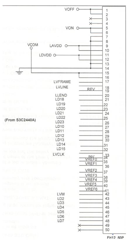
Figure12. Interfacing of Mono TFTLCD.
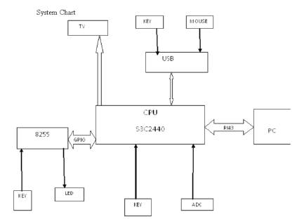
Figure 13. System chart
Here multi thread technique is used to collect AD data, control display and exchange information with Ethernet. As AD controller achieves the variation, the application set correct coordinate and calls GDI object bit method to display background bitmap.
But the conventional method is denied immediately, scene conversion is very slow and at the same time accompanied by a standstill. It is impossible to update vision frequency quickly on this hardware configuration with convectional methods. Microsoft provides C++ class that can be used to simplify writing display drivers. As convenient as these classes are, there are improvements that can be made to them that further simplify Display driver development and make display drivers more portable across Windows CE devices.
The output video data with following format 18bpp and 5:5:5,means one pixel should be expressed with two bytes and three color (Red, Green and Blue) which should be 5 bit, 5bit and 5bit, where FR is frame rate, BP is BPP,K is a parameter which is used to adjust FR. The other parameters should be set according to particular hardware. In this resolution is 900x700,BPP is 29. The bandwidth allocated to display equals 93.3M.System bus bandwidth is 100M
This paper presents a method to improve display speed on embedded system. Because of bandwidth limitation, system bus will be blocked up with large quantity of display data. This condition becomes much better when a software algorithm is adopted. As a result, the system is more efficient as well as expending more space in memory. In this paper, smooth and stable fast moving images are achieved. It provides a good reference to graphics development on embedded system.