The Design part in Very Large Scale Integration is an extremely complex task. It continually stresses the fact that the field is inherently multidisciplinary in nature. By keeping Integrated circuit as a reference, the Field Programmable Gate Array (FPGA) technology has become an advanced target for the implementation of real time algorithms suited to video image processing applications. The unique architecture of the FPGA has allowed the technology to be used in many applications encompassing all aspects of video image processing.
The algorithms like Linear Filtering based on a two dimensional convolution, and non-linear two dimensional rank order filters, Thresholding, Sobel Edge Detection etc., represent a basic set of image operations for a number of applications. In this paper, an implementation of linear image filtering using a FPGA Xilinx 13.1 Version, vertex-4 is presented. The FPGAbased system is accessed through a Matlab Graphical User Interface and Xilinx, which handles the communication setup. A HDL language is used for coding purpose. The results obtained from MATLAB simulations and the described FPGA-based implementation is presented.
Real-time image processing is difficult to achieve on a serial processor. This is due to several factors such as the large data set represented by the image, and the complex operations which may need to be performed on the image. At real-time video rates of 25 frames per second a single operation performed on every pixel of a 768 by 576 colour image (PAL frame) equates to 33 million operations per second. This does not take into account the overhead of storing and retrieving pixel values. Many image processing applications require that several operations be performed on each pixel in the image resulting in an even large number of operations per second. One alternative is to use a Field Programmable Gate Array (FPGA). Continual growth in the size and functionality of FPGAs over recent years has resulted in an increasing interest in their use as Implementation platforms for image processing applications, particularly real-time video processing [1]. An FPGA consists of a matrix of logic blocks that are allowing application specific hardware to be constructed, while at the same time maintaining the ability to change the functionality of the system with ease. As such, an FPGA offers a compromise between the flexibility of general purpose processors and the hardware-based speed of ASICs. [2, 3, 4]. There is currently a vast amount of software for digital image processing applications, for industrial or educational purposes. Among these, MATLAB has been extensively used becoming a standard mathematical language for engineers and scientists around the world [5, 6]. To synthesize the code on FPGA, a hardware description language, VHDL is used [7].
In this paper, a system based on the Xilinx FPGA vertex-4 has been used to implement an efficient mechanism image processing system for real time applications with educational purposes. MATLAB is used to convert image into pixel elements and that pixel values are accessed through VHDL file input output tasks and filtered image is accessed through Matlab.
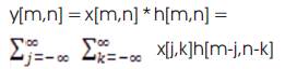
In a linear system, the output is obtained through the convolution of the input function with the system impulse response. In digital image processing, the impulse response is defined as a convolution mask or kernel with a size typically much less than the size of the input image. The window size of the convolution mask is related to the order of the system. 2D convolution is expressed as:
If the convolution mask is given by the following 3X3 matrix:
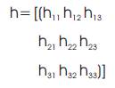
The output image is then obtained as,
According to the definition, the operations involved in a 2D convolution can be easily performed by addition and multiplication of the neighborhood inside of the convolution mask for each pixel in the input image.[8]. This can be implemented in HDL by using comparator, FIFO and registers.
There are several criteria in the development, demonstrations and applications of MSP (Max Signal Processing). First, the concepts must be presented clearly with little interfering information. Second the applications should be direct, flexible, and fast. Third, sound and visuals must be used to demonstrate concepts. Fourth, the demonstrations should allow the user to explore the topic by changing parameters. Fifth, a student should be able to look into the code to understand how it works. Sixth, the demonstrations should be compatible with as many computer platforms possible. And finally, the cost to students to be able to run the applications on their own computer should be minimal [9].
At the present time, many designers are carrying out several research projects whose objective is the development of specific circuits for the static and dynamic image processing. These developments are realized in devices such as FPGAs or ASIC, usually by means of standard hardware description languages such as VHDL. VHDL allows the use a single language throughout all the processes of design. Nevertheless, only this is not enough to do a successful project. Complex algorithms used to process images and image sequences make necessary to do simulations of his operation to verify the fulfillment of the specifications under which it has been designed. To test systems that process images it is necessary to feed the model with a complete set of signals and data. Current commercial VHDL/Verilog synthesis and simulation tools are equipped with utilities to create stimulus signals, but they have limited utility in applications that require a big amount of data such as image processors [10].
Figure 1 shows the block diagram for processing image in order to enhance the image quality. The FPGA kit is connected to a PC through the USB2 port. A MATLAB interface allows the user to open the image to be processed, setup the communication parameters, specify the required processing, send the input image, perform the required filtering mechanism and receive the corresponding result after the process. The operations are performed on a 64x64 size or 128x128 input gray image, organized in a linear form as shown in Figure 2. The module receiver shown in block diagram composed of a serial receiver module is represented in Figure 3. It shows that VHDL implementation block of window size operator which receives the input data in serial format for every rising edge of the clock, shows the parallel output result, and generates the memory address where the data is temporarily stored. The output is connected to the following module called single module. When the total number of the window size image elements has been received, a signal enables and it is convolved with masking which is shown in Figure 4 of convolution filter.
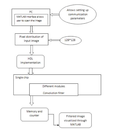
Figure 1. Block Diagram
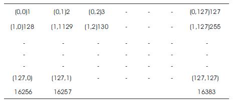
Figure 2. Pixels Distribution of input image
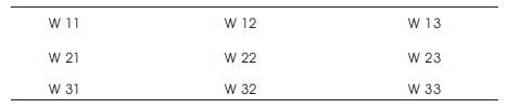
Figure 3. window size operator
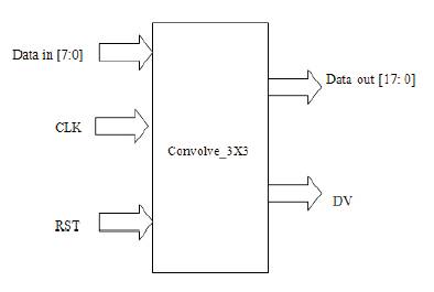
Figure 4. Top Module Implementation block
In similar way for 5x5 windows it requires 4 FIFO and still comparator and registers will be increased and occupies more area.
The top level FIFO module using VHDL implementation is shown in the Figure 5.
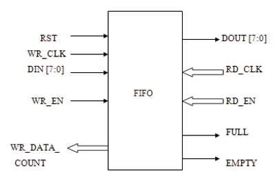
Figure 5. FIFO Module
From the FIFO module, the elements are convolved through the convolution filter and given to the MATLAB interface for displaying the filtered image which is discussed in section 5.
The design of the convolution algorithm in VHDL was a much more difficult problem. This was due to its use of more complex mathematics. For example, the rank order filter really just sorts the pixels in a window and outputs one of them, while the convolution algorithm uses adders, multipliers, and dividers to calculate its output. On FPGAs, use of mathematics tends to slow down performance. Many designers favor techniques that reduce the algorithm's dependency on complex mathematics. Still, since the mathematics used in convolution is simple, implementation of a convolution algorithm was an achievable goal. Yet another obstacle in this algorithm's design was implementing the capability to handle negative numbers. In a proper convolution algorithm, the mask can (and often does) consist of negative numbers. Effectively, the VHDL had to be written to handle these numbers by using signed data types. Signed data simply means t hat a negative number is interpreted into the 2's complement of its non -negative dual. This means that all vectors within the design must use an extra bit as compared to unsigned numbers. The extra bit always carries the sign of the number – 0 for a positive number, 1 for a negative number.
The valid output for the convolution algorithm occurs six clock cycles after the first window is valid. Since this design is pipelined and will run in the Mega hertz range, this kind of startup latency has very little effect on overall design speed. Table I shows a resource used for convolution filter synthesis.
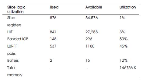
Table 1. Performance and Resources for convolution filter synthesis
Figure 6 shows the MATLAB graphical user interface designed for this system. The interface allows the user to select the image to convert into pixels and select the image to be processed in jpg or gray image format. According to the type of processing specified by the user, a 3X3 pixels operational mask is defined. If a convolution linear filter is selected, the coefficients define the system impulse response. If a rank order filter is required, the coefficients define sorting form. Once the operational mask coefficients are entered, the system is ready to send the information to the FPGA in order to perform the required processing, obtain the output image, and send it back to the local computer, displaying the result through the graphical user interface.
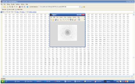
Figure 6. MATLAB image to Pixels
The size of the image grows linearly with pixel values. The different images are Tagged Image Format (TIF), RGB image, Binary Image, Gray colour image, etc. The memory size also depends on the type of the image.
Figure 7 shows a loading data from matlab window into Xilinx project window memory using VHDL. Table I shows a the memory usage. In order to filter the image, the system is operating at frequency 13.1 MHz, which gives an approximate execution time of 3.4ms.
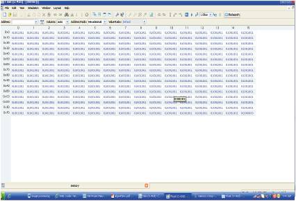
Figure 7. VHDL memory
The Figure 8 shows the simulation result for first in first out through window size operator. Figure 9 shows the simulation for convolution algorithm and Figure 10 shows the Filtered image through MATLAB Interface.
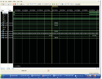
Figure 8. FIFO simulation data
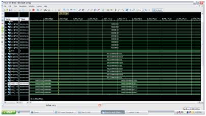
Figure 9. Convolution data
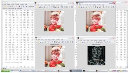
Figure 10. filtered Image
Finally the pin descriptions and FPGA loaded data is shown in Figure 11.
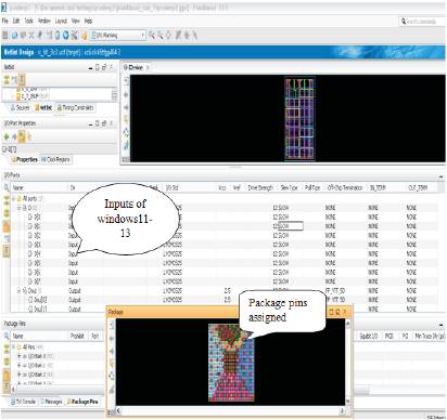
Figure 11. FPGA loading
The operation performed on 128 * 128 binary images or gray scale images, which is in linear form is shown in Figure 2. Image files tend to be large. We shall investigate the amount of information used in different image type of varying sizes. For example, suppose we consider a 512*512 binary image. The number of bits used in this image (assuming no compression, and neglecting, for the sake of discussion, any header information) is,
512* 512*1 = 262,144
= 32768 bytes
= 32.768 Kb
= 0.33 Mb
A gray scale image requires,
512*512*1 = 262,144
= 262.14Kb
An efficient image processing system can be developed for real time applications. The image filtering can be done based on 2D linear filtering and the resources that were used from FPGA have been listed. Image filtering implementation in VLSI domain is presented. The system takes advantages of the available resources in the Xilinx FPGA Vertex-4. A MATLAB graphical user interface allows the designer to operate the system in an ease way, through the basic required operations such as image manipulation, and setup of the communication parameters. With Matlab modelsim, GUI tool is used for verification purpose in an easy way. The FPGA-based realtime image processing system has been seemingly proved to be very good tool for further computer vision applications.
The first author would like to acknowledge Prof K R KINI, Professor & Head, Telecommunication, Sir MVIT, Bangalore for his advice and valuable suggestion.