1

This paper presents the design and implementation of signed-unsigned Modified Booth Encoding multiplier. Thus, the requirement of the modern computer system is a dedicated and very high speed multiplier unit that can perform multiplication operation on signed as well as unsigned numbers. The conventional Modified Booth Encoding (MBE) generates an irregular partial product array because of the extra partial product bit at the least significant bit position of each partial product row. The modified Booth Encoder circuit generates half the partial products in parallel, by extending sign bit of the operands and generating an additional partial product. The Carry Save Adder (CSA) tree and the final Carry Look Ahead (CLA) adder is used to speed up the multiplier operation. The resultant multiplier shows best performance than others since the proposed multiplier operates at GHz ranges.
In digital computing systems, multiplication is an arithmetic operation. The multiplication operation consists of producing partial products and then adding these partial products, the final product is obtained. Thus the speed of the multiplier depends on the number of partial product and the speed of the adder. Since the multipliers have a significant impact on the performance of the entire system, many high performance algorithms and architectures have been proposed [1-13]. Very high speed and dedicated multipliers are used in pipeline and vector computers. The high speed Booth multipliers and pipelined Booth multipliers are used for Digital Signal Processing (DSP) applications such as for multimedia and communication systems. High speed DSP computation applications such as Fast Fourier Transform (FFT) require additions and multiplications. The papers [1] [4] present a design methodology for high speed Booth encoded parallel multiplier. For partial product generation, a new Modified Booth Encoding (MBE) scheme is used to improve the performance of traditional MBE schemes. But this multiplier is only for signed number multiplication operation.
The conventional Modified Booth Encoding (MBE) generates an irregular partial product array because of the extra partial product bit at the least significant bit position of each partial product row. Therefore papers [2] [3] present a simple approach to generate a regular partial product array with fewer partial product rows and negligible overhead, there by lowering the complexity of partial product reduction and reducing the area, delay, and power of MBE multipliers. But the drawback of this multiplier is that it functions only for signed number operands.
The modified-Booth algorithm is extensively used for high-speed multiplier circuits. Once, when array multipliers were used, the reduced number of generated partial products significantly improved multiplier performance. In designs based on reduction trees with logarithmic logic depth, however, the reduced number of partial products has a limited impact on overall performance. The Baugh-Wooley algorithm [5] [8] is a different scheme for signed multiplication, but is not so widely adopted because it may be complicated to deploy on irregular reduction trees. Again the Baugh-Wooley algorithm is for only signed number multiplication. The array multipliers and Braun array multipliers [11] operate only on the unsigned numbers.
Thus, the requirement of the modern computer system is a dedicated and very high speed multiplier unit that can perform multiplication operation on signed as well as unsigned numbers. In this paper, the authors designed and implemented a dedicated multiplier unit that can perform multiplication operation on both signed and unsigned numbers, and this multiplier is called as SUMBE multiplier.
The new MBE recorder [1] was designed according to the following analysis. Table 1 presents the truth table of the new encoding scheme. The Z signal makes the output zero to compensate the incorrect X2_b and Neg signals. Figure 1 presents the circuit diagram of the encoder and decoder. The encoder generates X1_b, X2_b, and Z signals by encoding the three x-signals. The yLSB signal is the LSB of the y signal and is combined with x-signals to determine the Row_LSB and the Neg_cin signals. Similarly, yMSB is combined with x- signals to determine the sign extension signals. Figure 2 shows an overview of the partial product array for an 8 × 8 multiplier. The sign extension circuitry is developed in [12] and [13]. The conventional MBE partial product array has two drawbacks: 1) an additional partial product term at the (n-2)th bit position; 2) poor performance at the LSB-part. To rectify the two drawbacks, the LSB part of the partial product array is modified. Referring to Figure. 2a, the Row_LSB (gray circle) and the Neg_cin terms are combined and further simplified using Boolean minimization. The new equations for the Row_LSB and Neg_cin can be written as (1) and (2), respectively.

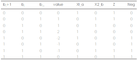
Table 1. Truth Table of MBe Scheme
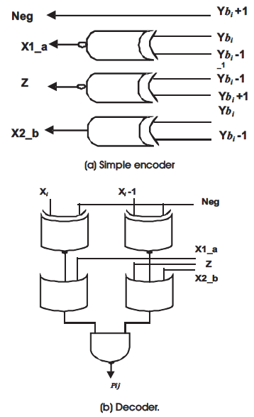
Figure 1. The Encoder and Decoder for the new MBE scheme.
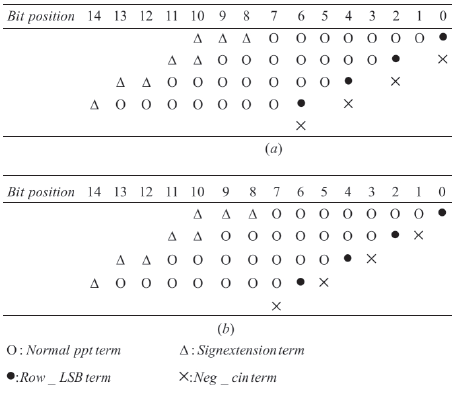
Figure 2. 8× 8 MBE partial product array. (a) Traditional MBE partial product array. (b) New MBE partial product array
Figure 2(a) has widely been adopted in parallel multipliers since it can reduce the number of partial product rows to be added by half, thus reducing the size and enhancing the speed of the reduction tree. However, as shown in Figure 1(a), the conventional MBE algorithm generates n/2 + 1 partial product rows rather than n/2 due to the extra partial product bit (neg bit) at the least significant bit position of each partial product row for negative encoding, leading to an irregular partial product array and a complex reduction tree.
Figure 2 shows. 8× 8 MBE partial product array. Figure (2a) is Traditional MBE partial product array and Figure (2b) is New MBE partial product array Therefore, the Modified Booth multipliers with a regular partial product array [2] produce a very regular partial product array, as shown in Figure 3. Not only each negi is shifted left and replaced by ci but also the last neg bit is removed. This approach reduces the partial product rows from n/2 + 1 to n/2 by incorporating the last neg bit into the sign extension bits of the first partial product row, and almost no overhead is introduced to the partial product generator. More regular partial product array and fewer partial product rows result in a small and fast reduction tree, so that the area, delay, and power of MBE multipliers can further be reduced.
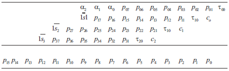
Figure 3. The partial product array for 8×8 multiplier
The main goal of this paper is to design and implement 8×8 multiplier for signed and unsigned numbers using MBE technique. Table 2 shows the truth table of MBE scheme. From Table 2 the MBE logic diagram is implemented as shown in Figure 4. Using the MBE logic and considering other conditions the Boolean expression for one bit partial product generator is given by the equation 3. Equation 3 is implemented as shown in Figure 5. The SUMBE multiplier does not separately consider the encoder and the decoder logic, but instead implemented as a single unit called partial product generator as shown in Figure 5. The negative partial products are converted into 2's complement by adding a negate (Ni) bit. An expression for negate bit is given by the Boolean equation 4.
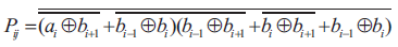
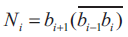
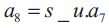
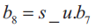
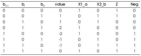
Table 2. Truth Table of MBE Scheme
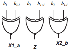
Figure 4. Logic diagram of MBE
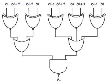
Figure 5. Logic diagram of 1-bit partial product generator
This equation is implemented as shown in Figure 6. The required signed extension to convert 2's complement signed multiplier into both signed-unsigned multiplier is given by the equations 5 and 6. For Boolean equations 5 and 6 the corresponding logic diagram is shown in Figure 7.
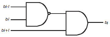
Figure 6. Logic diagram of negate bit generator

Figure 7. Logic diagram of sign converter.
The working principle of sign extension that converts signed multiplier to signed-unsigned multiplier is as follows. One bit control signal called signed-unsigned (s_u) bit is used to indicate whether the multiplication operation is signed number or unsigned number.
When Sign-unsign (s_u) = 0, it indicates unsigned number multiplication, and when s_u = 1, it indicates signed number multiplication. It is required that when the operation is unsigned multiplication, the sign extended bit of both multiplicand and multiplier should be extended with 0, that is a8 = a9 = b8 = b9 = 0. It is required that when the operation is signed multiplication, the sign extended bit depends on whether the multiplicand is negative or the multiplier is negative or both the operands are negative.
For this when the multiplicand operand is negative and multiplier operand is positive the sign extended bits should be generated as s_u = 1, a7 =1, b7 = 0, a8 = a9 =1, and b8 = b9 =0. And when the multiplicand operand is positive and muitplier operand is negative the sign extended bits should be generated as s_u = 1, a7 =0, , b7 = 1, a8 = a9=0, and b8 = b9 =1. Table 3 shows the SUMBE multiplier operation. Figure 8 shows the partial products generated by partial product generator circuit which is shown in Figure 5. There are 5-partial products with sign extension and negate bit Ni. All the 5-partial products are generated in parallel.
In Figure 8 there are 5-partial products namely X1, X2, X3, X4 and X5. These partial products are added by the Carry Save Adders (CSA) and the final stage is Carry Look ahead (CLA) adder as shown in Figure 9. Each CSA adder takes three inputs and produce sum and carry in parallel. There are three CSAs, and five partial products are added by the CSA tree and finally when there are only two outputs left, then finally CLA adder is used to produce the final result. Assuming each gate delay an unit delay, including partial product generator circuit delay, then the total through the CSA and CLA is 3+4 = 7 Unit delay. Thus with present Very Large Scale Integration (VLSI) the total delay is estimated around 0.7 nano second and the multiplier operates at giga hertz frequency.
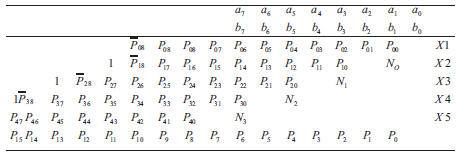
Figure 8. 8×8 multiplier for signed-unsigned number
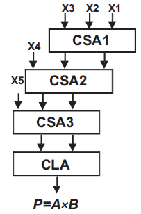
Figure 9. Partial product adder logic
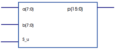
Figure 10. RTL view of 8×8 signed-unsigned multiplier
Verilog code is written to generate the required hardware and to produce the partial product, for CSA adder, and CLA adder. After the successful compilation, the RTL view generated is shown in Figure10.
Figure 11 shows the simulation result of signed-unsigned numbers. Figure 11(a) shows the simulation result of signed unsigned number in binary. Here when the control signal s_u = 0, the 8-bit operands are considered as unsigned and the product of 11111111 × 11111111 = 1111111000000001. And when the control signal s_u = 1, the 8-bit operands are considered as signed and the product of 11111111 × 11111111 = 0000000000000001.
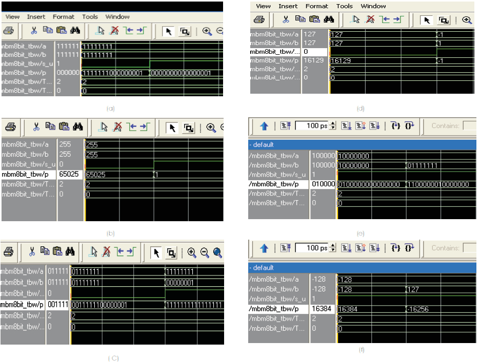
Figure 11. Simulation Result shows the signed - unsigned number in binary and decimal
Figure 11(b) shows the simulation result of unsigned operands in decimal i.e when the control signal s_u = 0, the 8-bit operands are considered as unsigned and the product of 11111111 (255) × 11111111 (255) = 1111111000000001 (65025), and when the control signal s_u = 1, the 8-bit operands are considered as signed and the product of 11111111 (-1) × 11111111 (-1) = 0000000000000001 (+1).
Figure 11(c) and Figure 11(d) shows the simulation result of signed- unsigned number in binary and decimal respectively. When s_u = 0, the 8-bit operands are unsigned and the product of 01111111 (127) × 01111111 (127) = 0011111100000001 (16129). And when the control signal s_u = 1, the 8-bit operands are signed and the product of 11111111 (-1) × 00000001 (+1) = 1111111111111111 (-1).
Figure 11(e) and Figure 11(f) shows the simulation result of signed- unsigned number in binary and decimal respectively. When s_u = 0, the 8-bit operands are unsigned and the product of 10000000 (128) × 10000000 (128) = 0100000000000000 (16384). And when the control signal s_u = 1, the 8-bit operands are signed and the product of 10000000 (-128) × 01111111 (+127) = 1100000010000000 (-16256).
The 8X8 MBE Multiplier reduces the number of partial product into half by using 3 Carry Save Adders and 1 Carry Look Ahead Adder based on radix-4 Modified Booth Algorithm. And it performs the multiplication operation for both signed and unsigned numbers. Finally it reduces the delay to 11.496ns and it operates the frequency to 86.98MHz. By using radix-8 MBE technique it reduces the number of partial products into n/3.For 8x8 bit multiplication using radix-8, Modified Booth encoding technique is used and then there are only 3 partial products and for that only 1 CSA and 1 CLA is required to produce the final product and also it reduces the delay to less than 11.496ns and increases the operating frequency to GHz range.