Figure 1. Basic configuration of BLDC motor
This paper presents a comparative study of various controllers for the speed control of BLDC Motor. The most commonly used controller for the speed control of motor is Proportional-Integral (P-I) controller. However, the P-I controller has some disadvantages such as: the high starting overshoot, sensitivity to controller gains and sluggish response due to sudden disturbance. So, the relatively new Integral-Proportional (I-P) controller is proposed to overcome the disadvantages of the P-I controller and the performance these controllers are compared with P, I, P-I and I-P controllers. Simulation results are presented and analyzed for all the controllers. It is observed that I-P controllers give better responses than the traditional P-I for the speed control of BLDC motor drives
The Brushless DC (BLDC) motor is rapidly gaining popularity by its utilization in various industries, such as appliances, automotive, aerospace, consumer, medical, industrial automation equipment and instrumentation. As the name implies, the BLDC motors do not use brushes for commutation; instead they are electronically commuted.. BLDC motors have many advantages over brushed DC motors and induction motors, a few of these are [1]
a. Better speed Vs torque characteristics
b. High dynamic response
c. High efficiency
d. Long operating life
e. Noiseless operation
Before now, several simulation models have been proposed for the analysis of BLDC motors drives. In this paper the authors propose a simulation model of a BLDC motor without using a controller, whose characteristics are compared with a model with Integral and Proportional controller. In this model the trapezoidal back EMF waveforms are modeled as a function of rotor position and the switching function concept is adopted to model the Voltage source inverter (VSI). This in turn results in obtaining the detailed voltage and current waveforms of the inverter.
Therefore, it can be expected that the developed simulation model can be an easy-to-design tool for the development of BLDC motor drives including control algorithms and topological variations with reduced computation time.
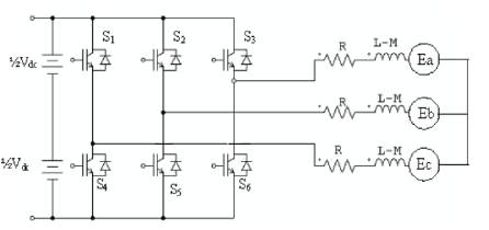
The BLDC motor is also referred to as an electronically commuted motor and, as there are no brushes on the rotor the commutation is performed electronically depending on the rotor position. The stator phase windings are inserted in the slots or can be wound as one coil on the magnetic pole. Figure1 shows the basic configuration of BLDC motor with converter circuit.
Figure 1. Basic configuration of BLDC motor
In DC Commutator motor, the current polarity is reversed by the commutator and the brushes, but in the brushless DC motor, the polarity reversal is performed by semiconductor switches which are to be switched in synchronization with the rotor position. Besides the higher reliability, the missing commutator brings another advantage. The commutator is also a limiting factor in the maximal speed of the DC motor. Therefore the BLDC motor can be employed in applications requiring high speed.
Replacement of a DC motor by a BLDC motor place higher demands on control algorithm and control circuit. Firstly, the BLDC motor is usually considered as a three phase system.
Thus, it has to be powered by a three phase power supply. Next, the rotor position must be known at certain angles, in order to align the applied voltage with the back-EMF. The alignment between the back-EMF and commutation events is very important. In this condition the motor behaves as a DC motor and runs at the best working point. But the drawbacks of the BLDC motor caused by necessity of power converter and rotor position measurement are balanced by excellent performance and reliability, and also by the ever-falling prices of power components and control circuits.
Modeling of a BLDC motor can be developed in the similar manner as a three-phase synchronous machine. Since there is a permanent magnet mounted on the rotor, some dynamic characteristics are different. Flux linkage from the rotor depends upon the magnet material. Therefore, saturation of magnetic flux linkage is typical for this kind of motors. As any typical three-phase motors, one structure of the BLDC motor is fed by a three-phase voltage source. The source is not necessarily to be sinusoidal. Square wave or other wave-shape can be applied as long as the peak voltage does not exceed the maximum voltage limit of the motor. Similarly, the model of the armature winding for the BLDC motor is expressed as follows:
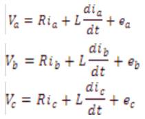
where
L is armature self inductance [H],
R is armature resistance [Ω],
Va ,Vb , Vc are terminal phase voltage [V],
ia , ib , ic are motor input current [A],
and ea , eb , ec are motor back emf [V].
In the 3-phase BLDC motor, the back-EMF is related to a function of rotor position and the back-EMF of each phase has 120o phase angle difference so equation of each phase should be as follows
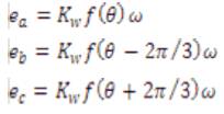
where
Kw is back EMF constant of one phase [V/rad.s-1),
θ is the electrical rotor angle [oe1.],,
ω is the rotor speed [rad.s-1].
The electrical rotor angle is equal to the mechanical rotor angle multiplied by the number of pole pairs p:

where
θm is mechanical rotor angle [rad].
Total torque output can be represented as summation of that of each phase. Next equation represents the total torque output:
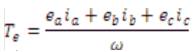
where
Te is the total torque output [Nm],
The equation of mechanical part is represented as follows:
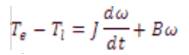
where
Ti is load torque [Nm],
J – inertia of rotor and couple shaft [Kgm2],
B – friction constant [Nms.rad-1].
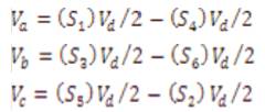
The converter block was developed using equations below [2, 3]
The block diagram of the drive with the P-I controller has one outer speed loop and one inner current loop, as shown in Figure 2. The speed error EN between the reference speed NR and the actual speed N of the motor is fed to the P-I controller, and the Kp and Ki are the proportional end integral gains of the P-I controller. The output of the P-I controller E1 acts as a current reference command to the motor, C1 is a simple proportional gain in the current loop and KCH is the gain of the GTO thyristor chopper , which is used as the power converter.
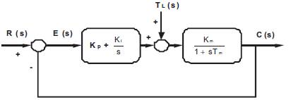
Figure 2. P-I Controller Structure
The P-I controller has the form
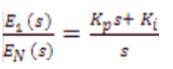
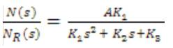
This is a phase-lag type of controller with the pole at the origin and makes the steady-state error in speed zero. The transfer function between the output speed N and the reference speed NR is given by
Where,
A = C1KCH K
K1 = RABTM + C1KCHBTM
K2 = RAB + K2 + C1KCHB + AKP
K3 = AK1
TM= J /B
K1 and KP are controller gains, and RA , B, TM , etc. are motor and feedback constants. The above equation introduces a zero, and therefore a higher overshoot is expected for a step change in speed reference.
The block diagram of the I-P controller has the proportional term KP moved to the speed feedback path shown in Figure3. There are three loops, one inner current loop, one speed feedback loop and one more feedback loop through the proportional gain KP . The speed error EN is fed to a pure integrator with gain K1 and the speed is feedback through a pure proportional gain KP .
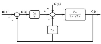
Figure 3. I-P Controller Structure
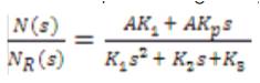
The transfer function between the output speed N and the reference speed NR is given by
When the authors compare the characteristic equations for both P-I and I-P controllers, the zero introduced by the P-I controller absent in the case of I-P controller, and thus the overshoot with an I-P controller is expected to be very small.
The simulation of a BLDC motor is done using software named Powersim (PSIM). PSIM is a simulation package specifically designed for power electronics and motor controls with fast simulation and user friendly interface. In addition, PSIM supports links to third-party software like MATLAB through custom DLL blocks.
The PSIM simulation package consists of the circuit schematic program PSIM, the simulator engine and the waveform processing program SIMVIEW. The simulation process is shown in Figure 4. Figure 5 shows the block diagram of a BLDC motor with a controller. [4]
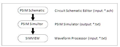
Figure 4. PSIM simulation process
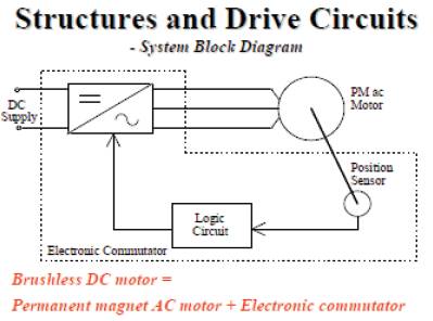
Figure 5. Block diagram of a BLDC motor with a controller
BLDC motor specifications used in simulation are shown in Table 1.
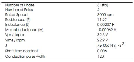
Table 1. Parameters of BLDC motor
In order to improve the performance characteristics of the motor, the speed of the motor is sensed and fed back to the controller. The controller helps in improving the performance of the motor by comparing the actual speed of the motor with the reference speed. The various types of controllers used for the simulation of a BLDC motor are Proportional (P) controller, Integral (I) controller, PI controller, IP controller etc.
In this paper the authors analyse the performance of the BLDC motor using a P controller, I controller, a PI controller and then comparing their characteristics with a IP controller.
Figure 6 shows the Simulink diagram used for the analysis of a BLDC motor using a P controller. The gain of the P controller is taken as KP = 0.2.
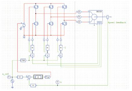
Figure 6. Simulink Diagram of BLDC Motor with a P controller
The speed response of a P controlled BLDC motor is shown in Figure 7. In which the actual speed of the rotor is compared with the reference speed. The reference speed of the motor is 3000 rpm where are the actual speed of the rotor attains a maximum value of 2911rpm at t = 0.0015s and slowly attains the constant speed.
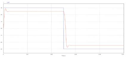
Figure 7. Speed response of a P controlled BLDC motor
Figure 8 shows the three phase current waveforms of the BLDC motor. From the phase current analysis of the motor we observe that with the sudden change in the direction of the rotor the phase currents are suddenly increased and decreased heavily.
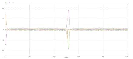
Figure 8. Current Waveforms of a P controlled BLDC motor
Figure9 shows the Simulink diagram used for the analysis of a BLDC motor using a I controller. The gain of the I controller is taken as K1 = 0.1.
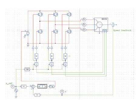
Figure 9. Simulink Diagram of BLDC Motor with a I Controller
The speed response of a I controlled BLDC motor is shown in Figure 10 in which the actual speed of the rotor is compared with the reference speed.
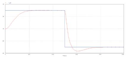
Figure 10. Speed response of a I controlled BLDC motor
The reference speed of the motor is 3000 rpm and the rotor of the motor slowly attains the reference speed at t= 0.08sec. Figure11 shows the phase current response of the I controlled BLDC motor.
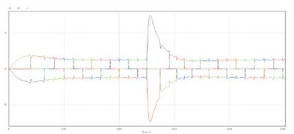
Figure 11. Current waveforms of a I controlled BLDC motor
Figure12 shows the model diagram used for the Simulation of BLDC motor using a PI controller. The control circuit elements, determines the switching action to be performed based on the rotor position feedback. The speed controller and hysteresis current controller are used to maintain the speed and the current at reference value.Figure13(a) shows the speed response of the PI controlled BLDC motor, in which the speed of the rotor is compared with the rated speed and Figure13(b) shows the current waveforms of a PI controlled BLDC motor.
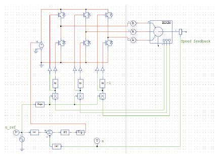
Figure12. Simulink Diagram of BLDC Motor with a PI controller
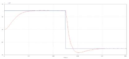
Figure 13(a). Speed response of a PI controlled BLDC motor
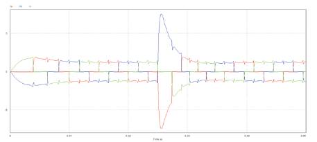
Figure 13(b). Current waveforms of a PI controlled BLDC motor
The applied rated speed is 3000 rpm. The motor is attaining a maximum speed of 3012rpm at t=0.015sec and minimum speed of -3650rpm at t=0.0304sec.
Figure 14 shows the model diagram used for the Simulation of BLDC motor using a IP controller.
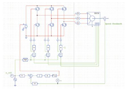
Figure 14. Simulink Diagram of BLDC Motor with a IP controller
Figure 15(a) shows the speed response of the IP controlled BLDC motor, in which the speed of the rotor is compared with the rated speed and Figure 15(b) shows the current waveforms of a IP controlled BLDC motor. The applied rated speed is 3000 rpm. The motor is attaining a maximum speed of 3653rpm at t=0.055sec and minimum speed of - 3667rpm at t=0.0304sec.
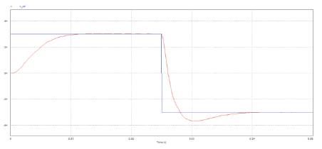
Figure 15(a). Speed response of a IP controlled BLDC motor
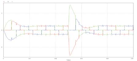
Figure 15(b). Current waveforms of a IP controlled BLDC motor
Figure 16 shows the comparison between the rotor rated speed and phase A current of a BLDC motor with a PI controller. From Figure the authors observe that when the motor direction is suddenly changed from steady state at t=0.25sec the phase current value drops to a value of 7.4A.
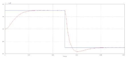
Figure 16(a). Speed response of a PI controlled BLDC motor
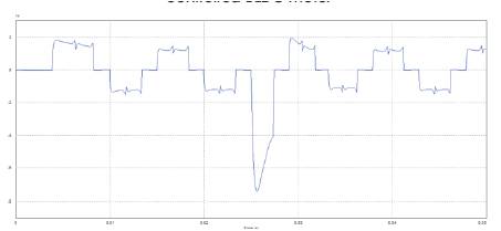
Figure 16(b). Phase A Current waveform of a PI controlled BLDC motor
Figure 17 shows the comparison between the rotor rated speed and phase A current of a BLDC motor with a IP controller. From Figure the authors observe that when the motor direction is suddenly changed from steady state at t=0.25sec the phase current value drops to a value of - 7.9A.-
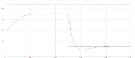
Figure 17(a). Speed response of a IP controlled BLDC motor
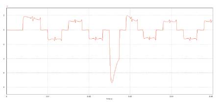
Figure 17(b). Phase A Current waveform of a IP controlled BLDC motor
The performance indices such as Settling time, Peak values of rotor speed and phase currents are shown in table 2 from the observations of the various response of the BLDC motor for the set speeds of 3000 rpm, 2000 rpm and 1000 rpm for P, I, PI and IP controllers. [5-7]
It is observed that PI controller starting response is good and overshoot is less for the given speed range when compared to the P controller. The improved performance of BLDC motor is obtained by minimizing the overshoot present in the transient response [6], and settling time using the PI controller. The transient deviation of the response from the set reference is found to be negligibly small along with a desirable reduction in settling time for the PI controller. The response is smooth and no oscillation in the case of PI controller. This is due to robust and accurate control structure of the PI controller. The results show significant improvement in the response of BLDC motor with the PI controller. [7-10]
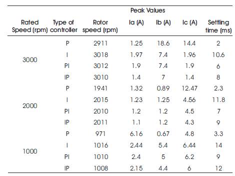
Table 2. Comparison of Performance indices between P controller, I controller PI controller and IP controller
In this paper, P controller, I controller, PI controller and IP controller have been employed for the speed control of BLDC motor. A performance comparison of P, I, PI and IP controllers has been carried out by several simulations. The results have shown that PI is better than that of P, I, IP controllers for any given speed. The results show that Powersim (PSIM) software is a good simulation tool for modeling and analyzing the brushless DC motor drives. The conclusion is that PI controller is found to be superior, more robust, faster and flexible and is insensitive to the parameter variations as compared with P controller, I controller and IP controller.