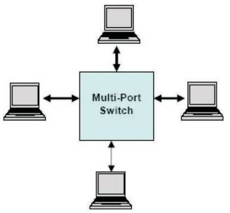
Figure 1. ‘Star' Ethernet Network Example
For the '24/7/365' world we live in, the user now demands the same services in the car as the office or home; emails, music, gaming and video, along with increased safety. A single IP-based network is the key, enabling the car to enter the World Wide Web. Implementing Ethernet at the OBD port now allows the car to interface to the World Wide Web, creating endless possibilities. For example, the port can easily be plugged into a wireless unit for remote diagnostics or downloads for in-car navigation, video or music, all from the comfort of the owner's home.
The next step is for Ethernet to form the backbone of the next generation automotive multi-media networks, carrying 'live' traffic. Standards such as IEEE 802.3AVB (Audi-Video Bridging) initially defined for Digital AV Home networking are being adapted to support the same real-time services in the car. Following this the ultimate goal would to converge other bus systems inside the car into a single common bus; Ethernet.
By combining Ethernet's proven ability to reliably transfer high bandwidths of data and with guaranteed Quality of Service (home/office), with real-time performance in extreme environments (Industrial control), the basis of many automotive needs is formed. Similarities in the emerging Digital Home and car networks go further than the possibility of sharing a common media. The same IEEE AVB (Audio/Video Bridging) standard to provide time synchronized low latency audio and video streaming around the home is also being scrutinized to form the basis of next generation automotive multi-media platform. The introduction of Ethernet into the car will most likely favour a combined 'ring' and 'star' topology approach.
As in Figure 1, a multiport switch is used to connect the multiple numbers of nodes in a 'star' topology. As in Figure 2 a 3-port switch is used to connect one node to the adjacent nodes to form a 'ring' topology. Figure 3 shows an example of a possible automotive Ethernet network with combined 'ring' and 'star' topology approach. Each physical media interface can independently be implemented using copper cabling or POF. Here, a central Gateway will interface to the On-Board Diagnostics (OBD) port and other available networks within the car, such as MOST or FlexRay. The Gateway unit can then act as bridge to the Head Unit, further connecting other systems such as Navigation, Vehicle Computer and Rear Seat Entertainment over a 'ring' topology.
Figure 1. ‘Star' Ethernet Network Example
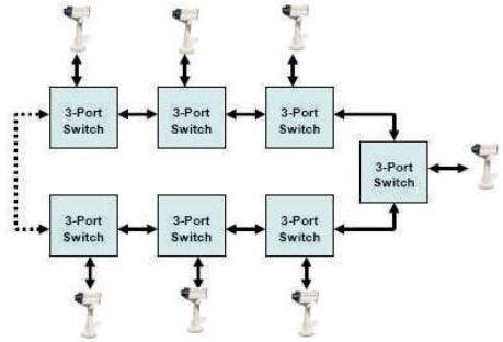
Figure 2. ‘Ring' Ethernet Network Example
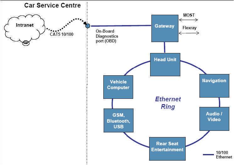
Figure 3. Example of a Basic Automotive Ethernet Network
Ethernet in the car initially will only be active when the engine is switched off, providing two main tasks via the OBD port: Diagnostics and Software Download for internal ECU static memory and hard disk(s). The introduction of Ethernet over lightweight Plastic Optical Fibre (POF) used in the 'ring' further adds to the lowering of costs due to weight. Using a standard Ethernet CAT5 cable to interface to the OBD port will allow service centers to seamlessly interface to either a laptop or their intranet to perform vehicle management diagnostics. Memory downloads for software updates also benefit from the 100Mbps (or 1000Mbps Gigabit Ethernet), full duplex bandwidth available by the network. Available bandwidth during memory download is vitally important. As the demand for increased processor intensive functionality in a car grows, so does the required memory. [R.M. Daoud, et. al, May 2006]. [N. Navet, et. al, June 2005].
Ethernet is the most widely used networking technology in an automobile repair shop's IT infrastructure. Automotive Ethernet solutions include:
While automobile repair shops usually diagnose and fix problems, they also update the software and data embedded in the various control devices inside the car via the On Board Diagnostics (OBD) connector.
Today this standardized connector only provides a slow communication interface so updating the software of a modern car via this interface takes hours, which significantly increases both repair times and costs. As a result, many car companies are working on an upgrade of the OBD connector to provide the car with a highperformance data interface for diagnostics and software downloads. The candidate of choice is Ethernet. This initiative is expected to lead to a new ISO/SAE standard that mandates Ethernet as part of the OBD interface for all cars. [T. Skeie, et.al., June 2002].
In today's vehicles, the electronics landscape is structured in “domains” – for instance, for body electronics, infotainment, vehicle motion management, occupant and pedestrian safety, and energy management. Each domain is controlled by a specific ECU which assumes the role of a central computer for this domain. Domains can in turn be structured into sub-domains. At the top level, they exchange data across a number of different networks, with a Central Gateway controlling the data flow as in Figure 4. Typically, the network technologies used for inter-domain communications are domain specific: The body electronics domain, for instance is connected to the Central Gateway by means of a CAN or High-speed CAN link, whereas in the energy management and in particular in the vehicle motion management domain, FlexRay might be the technology of choice.
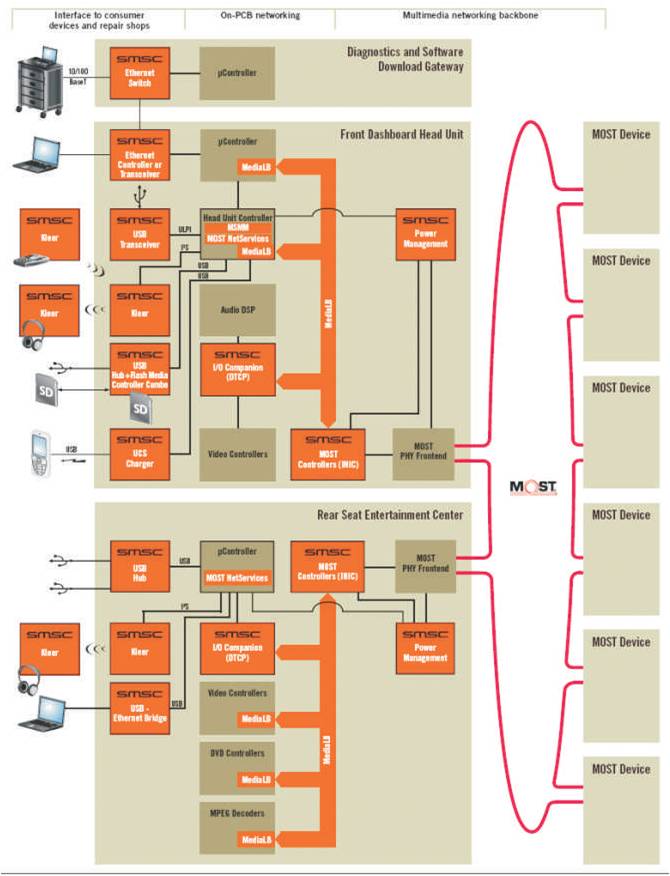
Figure 4. Ethernet Hardware for Automotive Applications
In the infotainment domain prevails the MOST bus. Its latest version MOST150 offers ample space for growing bandwidth requirements, which will be necessary, given the applications currently in the offing, which will enter the cars over the next couple of years; namely, In-vehicle infotainment with separate audio and video program for rear seat passengers, personal connectivity, vehicle internet integration or car-to-x connectivity. [F.L. Lian, et.al, Feb. 2001].
In this environment of increasing bandwidth demand and the necessity to dovetail software functions of the car and the outside world, Ethernet as the predominant networking technology in commercial IT will gain ground also in cars. At the same time, communication processes will increasingly use the Internet protocol stack (IP). Currently, the Diagnosis over IP (DoIP) standard is being worked, remote diagnosis and location based services enhancing the navigation system functionality. [R.M. Daoud, et.al., December 2003, 2004] .
The LAN89218 provides a simple, parallel host bus interface to the typical automotive embedded microcontrollers used inside a car. It can function as a network branch to the outside world connecting the car to a personal computer, diagnostic tool or a complex Ethernet network in the repair shop with power management, wake-on-LAN support allows network to wake-up electronics devices from sleep state, multiple low-power modes and built-in flow control support.
Phase 1: Proof of Concept
Implement test bench in laboratory and evaluate prototype hardware for functionality.
Phase 2: Engineering Optimization
Engineering development for possible product application.
Vehicle diagnostics are highly desired by automotive OEMS to troubleshoot vehicle problems at automotive OEM assembly lines and dealer service stations. While automobile repair shops usually diagnose and fix problems, they also update the software and data embedded in the various control devices inside the car via the On Board Diagnostics (OBD) connector.
Today this standardized connector only provides a slow communication interface so updating the software of a modern car via this interface takes hours, which significantly increases both repair times and costs. As a result, many car companies are working on an upgrade of the OBD connector to provide the car with a highperformance data interface for diagnostics and software downloads. No physical diagnostics exist for CAN and only ring break diagnostics exist for MOST.
On the other hand, modern Ethernet PHYs have substantial physical layer diagnostic capabilities which include: automatic detection and compensation of swapped pairs, cable breaks, and detection and compensation for links and impedance mismatches which can reduce bandwidth. Utilizing these commonplace Ethernet diagnostics, both assembly and service issues can be more quickly found and fixed. The candidate of choice is Ethernet. This initiative is expected to lead to a new ISO/SAE standard that mandates Ethernet as part of the OBD interface for all cars.