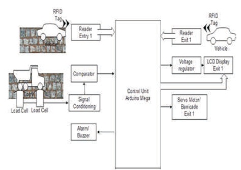
Figure 1. Control Unit for One Entry and Exit Point
The problem of managing smart toll lanes is one of the crucial topics of researchers and transportation industry. This paper provides an insight to various strategies involved in Smart Toll Collection System (STCS). One of the most widely used techniques for STCS is the Radio Frequency Identification (RFID) technique. A small prototype hardware realization of STCS is delineated to make the basics discernible. This paper describes the toll collection system based on distance travelled by the vehicle using RFID technology. The vehicle will hold a unique identification number assigned to the vehicle by traffic governing authority. All basic information as well as prepaid account details to ensure payment against toll tax incurred, is stored in the data base of the STCS. The unique tag number is read by the RFID reader at both entry and exit of the toll road and gate number will be stored in data base. At the time of exit, the distance will be calculated by the microcontroller. The billing amount is then displayed, balance is deducted from the prepaid balance, and new balance is updated. This paper is a short communication to enable a novice to decipher the details involved in STCS in a facile manner.
Road transportation system has a paramount impetus on realization of Smart city concept and development of a country. As automobile industry is manufacturing variety of vehicles at affordable rates, traffic on roads is profoundly increasing day by day. Managing traffic and toll collection is an onerous and challenging task for road transport authorities. Manual collection of tolls is the simplest method, but leads to traffic congestion, wastage of fuel due to waiting period, increased release of harmful emissions to the environment, etc. (Khan, Yakzan, & Ali, 2011; Laghari, Memon, & Pathan, 2012; Win, Nwe, & Latt, 2014; Satyasrikanth, Penna, & Bolla, 2016). As reported in (TCI, 2016) there is an immediate attention needed towards toll plazas and the toll collection techniques in India. The report narrates the exigency of Electronic Toll Collection (ETC) method as vital step towards minimizing delays due to the stoppages at toll gates. Only countable Toll plazas in India are practicing smart toll collection technique. India dawdles in the field of telematics as compared to the other BRICS countries (Sreekumar, Meena, & Shahabudeen, 2014). RFID technique is extensively used in STCS (Landt, 2005; Michael & McCathie, 2005; Yoon, Chung, & Lee, 2008; Yang, Saigal, & and Zhou, 2012). Also, to combat air pollution and promote carpooling, separate toll lanes can be reserved for high occupancy vehicles (Rosencranz, 2017).
The details of various frequency ranges associated with RFID passive tags are 125 KHz and 134.3 KHz for low frequency with distance up to 30 cm, 13.56 MHz for high frequency with distance up to 1.5 m and 860 to 960 MHz for ultra-high frequency with distance between 1 to 16 m (SkyRFID Inc., 2019). It has been reported in early works (Khali, Araar, Abdulla, 2014; Tentzeris, 2011) that RFID tags which can be detected certainly, at a distance of 35 m are available and the speed at which the data can be read is up to 167.7kph for 900 MHz tags.
The basic concept of toll collection system using RFID involves an RFID tag affixed on each vehicle. The information stored in the tag is unique to each vehicle and is read by an RFID reader appropriately positioned at the toll gate (Khan et al., 2011; Ting, Tsang, & Tse, 2013). As the vehicle surpasses the reader, a relevant amount is deducted from the account of the already registered owner and the balance is updated accordingly. Thus making the process more transparent, reliable and reduce the toll theft.
The brand name that is used to extend ETC throughout the country is 'FASTag'. Axis bank a t of them in the state of Tamil Nadu, Haryana, Punjab, Uttar Pradesh, Delhi, and Gujarat. Many states are yet to be equipped with ETC facility. It was reported that about 450 vehicles per hour can be handled by manual collection system, however ETC can check out 1200 vehicles/ hour (Electronic tool collection on highway: NHAI signs pact, 2014). ETC lanes reduce detrimental emissions of CO, Nitrogen oxide, etc., from vehicles to the atmosphere thereby preserving green environment.
RFID technique is a widely used method for military applications, industrial manufacturing procedures, tracking, timing events, and supply chains (Landt, 2005; Michael & McCathie, 2005). As this technique is a noncontact type, it is a convenient method for applications involving objects in motion (Yoon, et al., 2008). An RFID based toll collection method was proposed using 13.56 MHz passive RFID and a PIC Microcontroller (Win et al., 2014). A GUI was also part of implementation that enable the users to register and update the amount of balance.
The common methods of collecting toll tax are as follows
In 1990s, the toll plazas were manually controlled, where four members were required in a booth, two of them to open and close the gates and the other two for reception of money, tracking data, etc. Then semi-automatic toll plaza came up where data was stored in computers and gate operation was automatic, which requires only one member per booth.
Next, an Automatic toll collection system based on smart cards and RFIDs was developed. Here, only one person is required in a station to monitor the smooth operation.
In the conventional manual method, one person collects money and issues a receipt. In the Smart Card method, a person needs to show the smart card to the system installed at the toll tax booth to open the gate. Third and the latest is RFID tag-based toll collection, where toll is deducted automatically from prepaid balance. In the first two methods, the vehicle needs to be stopped at the toll booth, which leads to queuing up of the vehicles. However, in this method, the vehicles need not stop for payment, which is one of the greatest advantages that enhances customer experience.
The pricing scheme for Toll collection can be of three types (Yang, et al., 2012):
The third method is found to be more reasonable than the others (Yang et al., 2012).
In order to realize a successful and smart toll collection system, the following points are crucial.
There are four significant components of smart Toll collection system (WSTC, 2006), which are listed as below.
A separate set of tags need to be issued to exempt green vehicles, special vehicles, etc.
Certain laws must be enforced to impose penalties when rules are violated. Also, an authorized personnel must be deployed to check for the violation of ETC rules in addition to electronic means of support. The following may be few of the threats for implementing an ETC system.
The control unit in the prototype described in this section is designed using Arduino Mega and RFID. The prototype is developed for four toll gates considering two entry points and two exit points for vehicles. Arduino Mega has key features of 54 digital input/output pins, such as 14 PWM outputs, 16 analog inputs, 4 UARTs and Serial peripheral Interface (SPI), etc. (Arduino Mega 2560, 2018). The RFID readers are located at all the Entry and Exit points along with the Control unit and LCDs. In the prototype, the LCDs and motors are only shown at the exit points. The SPI is used to communicate with RFID readers in Master Input Slave Output mode. Using SPI, it is possible to have many RFID readers interfaced with one control unit to simulate Smart toll collection at all the four gates, where each of the RFID readers can be selected using the respective select line during communication.
The schematic with a control unit for one entry and one exit point is shown in Figure 1 and a simplified realization of a prototype using Arduino Mega and RFID reader RC552 is shown for two entry and exit points is shown in Figure 2. The load cell input has been simulated using an Arduino software, by reading the I/O pin, logic zero identified as no overload and Logic high identified as overload condition. If a match is found between the logic entered in the program, overload condition is displayed on the monitor. Each toll gate is assumed to have a unique identification number known as gate address number. The algorithm used with smart toll collection stores and updates Gate numbers, calculates the distance between them and the fare charged, as the vehicle enters through or exits from the toll gate. All the control units at the four Toll gates are assumed to be interconnected through a master control unit. Also, the heavy-duty vehicles carry overloading goods and damage the roads to a greater extent, to check against such situations. Load cell sensors are installed at the entrance of the toll gate to indicate the overloading condition of the control unit. Such vehicles must be penalized with extra charge. The control unit has the information of all registered/ unregistered vehicles, the details of all the account holders with insufficient balance, the RFID tag IDs corresponding to the registered green vehicles/ special vehicles, viz., ambulances, VIP vehicles, etc.
Figure 1. Control Unit for One Entry and Exit Point
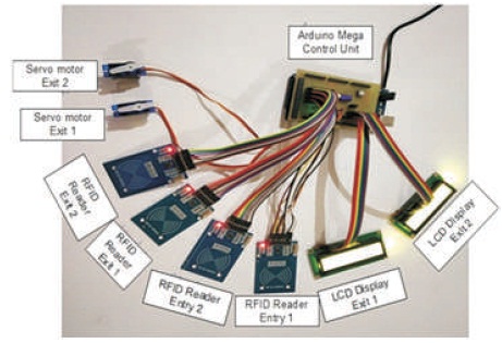
Figure 2. Prototype using Arduino Mega
When a vehicle arrives at a toll gate (say Entry 1), the tag of the vehicle is read by the reader. The gate address number is updated and the control unit compares the tag ID with the IDs already available in the list. If a match is found as a special vehicle or in the registered vehicles list with appropriate balance in the account, the vehicle is allowed to move without stopping, else the barricade is operated to stop the vehicle by sending control signal to servomotor at the gate and suitable actions may be taken as listed below.
When the vehicle reaches Exit gate (say Exit 2), the control unit obtains the gate address number of the previous and current toll gates and automatically calculates the toll tax according to the tariff set based on distance, deducts from the account, and updates the account. The tag information, entry and exit gates involved and the fare calculated are displayed as shown in Figures 3 and 4. A simplified sequence of the enhanced smart toll collection system is given in the flowchart as shown in Figure 5.
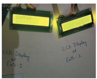
Figure 3. LCD Display for Distance Between Entry 1 and Exit 2
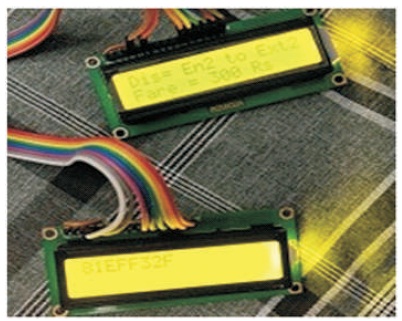
Figure 4. LCD Display for Distance Between Entry 2 and Exit 2
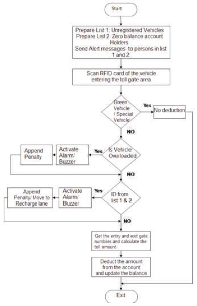
Figure 5. Flow Chart of Prototype Smart Toll Collection System
This method gives the passenger a clear information about the distance travelled and toll fare collected accordingly, which is deducted automatically from the prepaid balance.
The STCS configuration mainly involves the following:
Enhancement to the existing technique may be accomplished by including additional checks for enforcement, namely
The Global Positioning System (GPS) and Global System for Mobile communication (GSM) are used for the enhancement of STCS.
The smart toll collection system based on distance travelled by the vehicle uses RFID technology in expressway for toll collection has been described in this paper. The STCS has several benefits like low cost, high security, anti-theft of toll, efficiency, consumer satisfaction, etc. In India, road traffic is considerable, but very few toll plazas run ETC. This method tackles the most common grievance of customers, that they would have to pay toll for the entire toll road and not for the distance travelled. A simplified prototype has been designed using Arduino Mega 2560 for two Entry and Exit gates, wherein the toll tax is deduced based on the distance travelled by the vehicle. STCS improves the problem of theft in toll tax, wastage of fuel and time, also prevents the long queues in toll gate, air pollution, etc. This system improves the customer reliability and losses due to toll theft would also be compensated. It is an appropriate time to promote STCS in India and make common people aware about the benefits of STCS. This paper is one of the stepping stones in the above regard.