(1)
In the present time, the multi-phase Permanent Magnet Synchronous Machines (PMSMs) are being popular in the industries with efficient performance. In future, the multi-phase Permanent Magnet (PM) synchronous machines may be used in the variable speed drive applications, especially in renewable energy generation. Therefore, an accurate simulation model is needed for variable speed applications of PMSMs. Therefore, in this paper, an attempt has been made to make variable speed PMSMs simulation models in the latest MATLAB/Simulation environment with effective performance. The three phase and five phase variable speed PMSM machines models have been developed and both the performances have been compared. For performance comparison, three motor parameters have been used; these are stator currents, rotor speed, and electromagnetic torque. In the simulation models, two control loops have been used for efficient performance of the motor. The inner loop is used to control the speed of the motor and outer loop is used to control stator currents. The PI controller has also been used for motor controlling purpose. Finally, the authors state that the five phase variable speed PMSM motor model gives encouraging results as compared to three phase PMSM motor.
In recent years, for energy conversion, the magnetic and thermal capabilities of the permanent magnet have been considerably increased by employing the high-coercive permanent magnet material (Huixian & Shihua, 2012; Nagamani & Somanatham, 2016; Choi et al., 2009; Milanesi, 2009). The multi-phase machines are used in many industrial applications, such as ship propulsion, electric and hybrid electric vehicles (traction), aircraft, locomotive traction, aerospace, and other high power applications (Pillay & Krishnan, 1991). Since, the permanent magnet motors are generally of two types. First is Brushless DC motor with trapezoidal back EMF and second is Brushless DC motor with sinusoidal back EMF. Though, permanent magnet synchronous motor is a brushless motor with sinusoidal back EMF. When the motor is rotated externally the back EMF waveform measured at the terminals of PMSM will be sinusoidal (Pillay & Krishnan, 1991; Mani, 2006; Siddiqui et al., 2017a; 2017b).
The torque ripple is less in PMSM motor with sinusoidal input supply as compared to permanent magnet brushless DC motor having trapezoidal back EMF (Pillay & Krishnan, 1989). The main applications of PMSM are: AC servo system, aerospace, and military applications because of its advantages, such as quick response, high efficiency, excellent controlling, small-size, light-weight, and lesser noise (Pillay & Krishnan, 1991).
The PMSM contains very good characteristics, such as lesser volume, lightweight, small inertia, and high efficiency. Therefore, the torque to inertia ratio of PMSM motor is high and also with high volume ratio. The PMSM motor is maintenance free and controlling of it is also easy (Huixian & Shihua, 2012; Zhao & Lipo, 1996).
From second half of 1990s, multiphase variable speed drives have been receiving large interest in many industrial applications. The theoretical and technical reasons to use multi-phase machines over three phase machines are as follows (Choi et al., 2009; Zhao & Lipo, 1996; Thakur, 2016):
In this paper, the above stated theoretical and technical features of permanent magnet synchronous machines have been verified by the proposed simulation models. The mathematical modelling of PMSM has also been discussed. The main aim of this paper is to design variable speed three and five phase PMSMs machines with their improved features and characteristics. In the simulation model, two control techniques have been used simultaneously for controlling the motor to achieve efficient performance.
In this section, the mathematical modelling of permanent magnet synchronous motor has been discussed with the help of Park's transformation theor y. The Park's transformation theory is used to transform 3-phase abc into 2-phase dq model.
The damper winding is not used for developing the model with the help of reference frame. Some assumptions are considered for developing the model, such as induced EMF sinusoidal, hysteresis and eddy currents losses negligible, no field current dynamics, and neglected saturation.
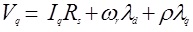
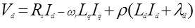
The voltage equations in q and d-axis are given in equations (1) and (2):
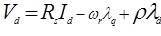
where

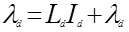
Equations (1) and (2) are substituted in equations (3) and (4):
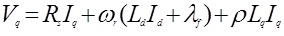
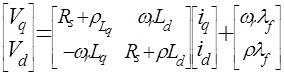
Equations (5) and (6) can be written in the matrix form as follows:
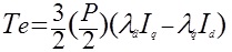
The electromagnetic torque developed in the motor is referred through equation (8):
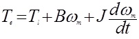
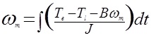
The mechanical torque is shown by equation (9):
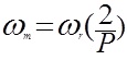
The obtained rotor mechanical speed is given in equation (10) and (11):
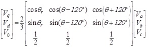
The Park's transformation is used in dynamic d-q modeling for the study transient and steady state of the motor. On conversion of the phase voltages variables Vabc to Vdq0- variables in reference frame, the following equation is obtained:
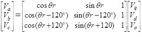
On converting the voltage variables Vdq0 to Vabc, the following equation is obtained:
Equations (1 to 13) have demonstrated the complete mathematical modeling of the permanent magnet synchronous motor.
The simulation model of 3-Phase PMSM is given in Figure 1.
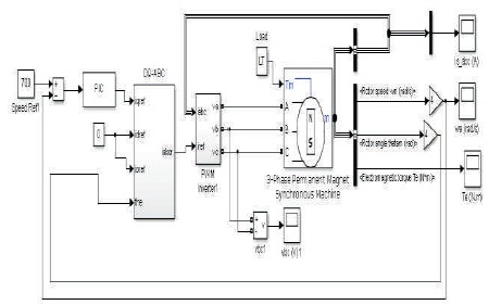
Figure 1. Simulation Model of Three Phase Permanent Magnet Synchronous Machine
The sub models of this complete simulation model is:
The motor configurations of used PMSM motor are:
The motor parameters of used PMSM are:
The Model of PI Controller (PIC) is shown in Figure 2. The value of the Proportion (P) and Integral (I) is set at 0.4 and 3, respectively. The minimum and maximum output is set as -150 to +150.
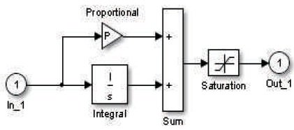
Figure 2. Model of Proportional Integral Control
The dq-abc transformation is done by the following sub model as shown in Figure 3. This sub model has been made only for the operation of healthy phases.
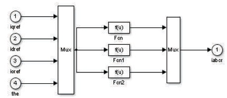
Figure 3. Model of dq-abc Transformation
The PWM inverter model is as shown in Figure 4. The PWM inverters are built entirely with standard Simulink blocks set. From Figure 4, it can be understood that the inverter output goes through controlled voltage source block before it is applied to PMSM stator winding.
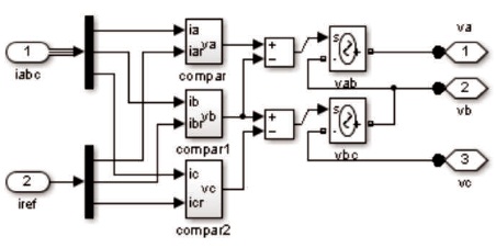
Figure 4. Model of Pulse Width Modulated Inverter
The load torque applied on the machine shaft is 7 N.m. This load torque is fixed in both cases, which means for three phase as well as five phase PM synchronous motor machines. In the simulation model (Figure 1), two control loops are used for regulation purpose. The inner loop is used to regulate the stator currents of the motor, whereas the outer loop is used to control speed of the motor. The machine starts under all healthy phases (normal operation).
The results obtained from three phase PMSM machine model are as shown in Figure 5 (a-c). Three signals are used for analysis purposes, such as three phase stator currents, rotor speed, and developed electromagnetic torque. The rotor speed achieved is 700 rad/s nominal value, but with large harmonics. From Figure 5(c), the electromagnetic torque contains large ripples, where consequently harmonics will be increased. From Figure 5(a-c), one can observe that all signals are reached in the steady state condition after 0.02 seconds time.
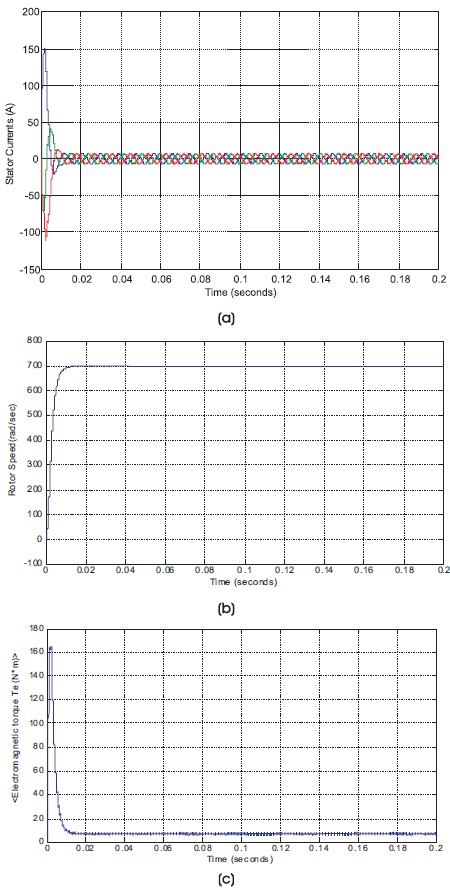
Figure 5. Signals of Three Phase Motor in Healthy Phases (a) Three Phase Stator Currents, (b) Rotor Speed, (c) Electromagnetic Torque
The result of the inverter voltage is as shown in Figure 6. From Figure 6, one may understand that the rated DC voltage is achieved, i.e. 300 Volt. This voltage is achieved in phase 'bc'.
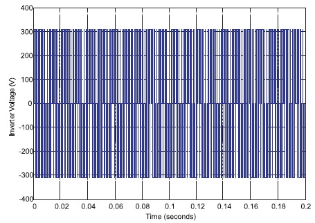
Figure 6. Line-to-Line Voltage in Phases ‘bc’
The complete simulation model of five phase permanent magnet synchronous machine is shown in Figure 7. The motor configuration and parameters are same as discussed for three phase permanent synchronous machine.
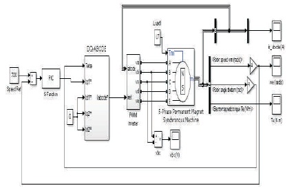
Figure 7. Simulation Model of Five Phase Permanent Magnet Synchronous Machine
The Model of PI Controller (PIC) is shown in Figure 8. The value of the Proportion (P) and Integral (I) is set at 20 and 11, respectively. The minimum and maximum output is set as -150 to +150.
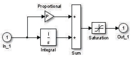
Figure 8. Model of Proportional Integral Control
The dq-abc transformation is done by the following sub model as shown in Figure 9. In the starting of the motor, it will run in the healthy phases.
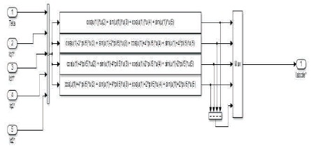
Figure 9. Model of dq-abc Transformation
The PWM inverter model is as shown in Figure 10. The PWM inverters are built entirely with standard Simulink blocks set. From Figure 10, it may be understood that the inverter output goes through controlled voltage source block before it is applied to PMSM stator winding.
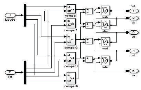
Figure 10. Sub Model of Pulse Width Modulated Inverter
The load torque applied on the machine shaft is 7 N.m. The same fixed load torque is used for three phase machine as well as five phase machine. In the simulation model (Figure 7), two control loops are used for regulation purpose. The inner loop is used to regulate the stator currents of the motor whereas the outer loop is used to control speed of the motor.
The results obtained from five phase PMSM machine model are as shown in Figures 11 (a-c). Three signals are used for analysis purpose, such as three phase stator currents, rotor speed, and developed electromagnetic torque. The rotor speed achieved is 700 rad/s, which is a nominal value, but with very less harmonics. The influence of PWM inverter in the simulation model has been significantly reduced. If we observe the result of electromagnetic torque, one can say that a much smoother electromagnetic torque is obtained. One can observe that all signals are reached in the steady state condition before 0.02 second time with much efficient performance.
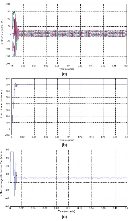
Figure 11. Signals of Five Phase Motor (a) Five Phase Stator Currents, (b) Rotor Speed, (c) Electromagnetic Torque
The result of the inverter voltage is as shown in Figure 12. From Figure 12, one may understand that the rated DC voltage is achieved, i.e. 300 Volt. This voltage is achieved in phase 'bc'.
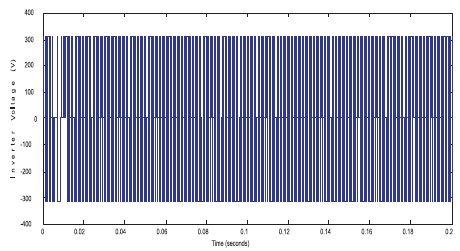
Figure 12. Line-to-Line Voltage in Phases ‘bc’
Therefore, after observing results of three phase machine and five phase machine, one may say that the five phase machine gives better results as compared to three phase machine with fewer harmonic.
From simulation results, following advantages have been observed as compared to three phase machine:
Therefore, in future multi-phase machines will be preferred in the industries for efficient performance.
In this section, the performance comparison of 3-phase and 5-phase PMSMs has been done through simulation results. The comparison has been done on the basis of some important motor parameters as shown in Table 1.
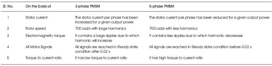
Table 1. Performance Comparison of 3 and 5 Phase PMSMS
In this research paper, the modeling and simulation of three and five phase permanent magnet synchronous motor drives for healthy phases has been discussed. From obtained results of three phase and five phase machines, it can be concluded that the five phase machine gives encouraging results rather than 3 phase machine. From five phase machine, one can achieve very good speed regulation as compared to three phase machine. The five phase machine contains a lot of advantages, such as high torque-to-current ratio, large power-to-weight ratio, high efficiency, high-power factor, high fault tolerance, robustness, and so forth, multiphase PMSMs have been paid more attention in high-power and high-reliability applications.
Discussed simulation models will be used in future for health monitoring of PMSM motor such as open phase fault and inter-turn fault by advanced Digital Signal Processing (DSP) Techniques. These simulation models may also be used in various power electronics and drives applications, and experimental analysis of these models is extremely needed for validation of the obtained results.