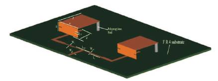
Figure 1. 2x1 Array of PILPA
Microstrip antennas are the ones that fulfill most of the wireless system requirements. These antennas are widely used on base stations as well as handsets. The microstrip patch antennas have increasingly wide range of applications in the wireless communication system due to their great advantages. Planar Inverted L Patch (PILP) Antenna is a good candidate for achieving compact microstrip antennas. In addition to compact operation, this design is also suitable for dual-frequency operation. To satisfy the needs of certain wireless communication systems, it is required to design and develop the antenna arrays to obtain the increase in gain and enhancement in the bandwidth. The 2x1 element arrays of microstrip line fed shorted patch antennas are developed. The experimental study shows that the arrays offer considerable increase in gain and enhancement in the bandwidth.
Microstrip antenna Measurement System Analysis (MSA) technology is the most rapidly developing topic in the antenna field receiving the creative attentions of academic, industrial and professional engineers and researchers throughout the world (Balanis, 1982). As the microstrip antenna is 'planar' in configurations, it enjoys all the advantages of printed circuit technology. It has significant merits of small size, lightweight, low cost, low volume, and easy to be fabricated (Wong, 2002; Yang, 1994). However, the MSAs show narrow impedance bandwidth, which is one of the main drawbacks. Numbers of studies have been reported in the literature for enhancing the impedance bandwidth of MSAs (Gao and Sambell, 2005; Abidin, 2012; Ghorbani and Waterhouse, 2004; Veerendra et al., 2014). Further, dual and triple band antennas are attractive for many military and commercial applications, where it is desirable to have a single antenna that can be dynamically reconfigured to transmit and/or receive on multiple frequency bands, particularly in SAR (Veerendra et al., 2015, 2016a; Cao et al., 2015). Dual and triple band antennas are realized by many methods (Veerendra and Bakhar, 2017). These methods use larger area of the substrate (Wax and Sheinvald, 1994). But in this paper a simple concept has been used by a 2x1 Planar Inverted L-patch Antenna array (PILPA) to get triple band operation, which also reduces the overall size of antenna to a greater extent.
The PIL Patch Antenna is a decent contender for accomplishing reduced microstrip antennas (Veerendra, 2016a). Notwithstanding smaller task, this outline is likewise reasonable for double recurrence activity. The PIL fix has an aggregate length of L+h and comprises of an even segment (length L) and a vertical bit (length h). The level bit is chosen to be a square fix having measurements of L x L, and is bolstered by plastic posts with a stature of 'h' over a grounded substrate. The grounded substrate has a thickness of 'h' and relative permittivity εr on which a 50 microstrip encourage line is printed.
The PIL fix is trotted over the microstrip nourish line with the edge of the fix's vertical part specifically associated with the bolster line. The part of the bolster line beneath the fix's even segment has a length of 'd' which is utilized as tuning stub for accomplishing great impedance coordinating for the PIL fix radio wire. The ideal length 'd' is observed to be around 40% of the aggregate length of the PIL fix, i.e. d = 0.4 (L + h). Keeping in mind the end goal to acquire different recurrence proportions of the two resounding frequencies, two indistinguishable openings having measurements l x w are embedded at the non transmitting edges of the PIL fix's vertical bit. The two embedded openings cause diverse winding consequences for the energized fix surface current ways of the two thunderous frequencies. Accordingly different recurrence proportions can be gotten with the choice of different opening measurements. Models of the outline have been built utilizing dainty copper sheet on a Glass epoxy substrate.
A 2x1 exhibit of PILPA is built utilizing the plan parameters of a solitary component receiving wire. The reception apparatus cluster setup with the nourish plan appeared in Figure 1 comprises of a 50 microstrip line of length L50 and width W50, which is associated with a 100 microstrip line of length L100 and width W100 to frame a two way control divider. A coordinating quarter wave transformer of length L and width W is associated between 100 sustain line and t t mid-purpose of the transmitting components keeping in mind the end goal to guarantee idealize impedance coordinating. Outline parameters are specified in Table 1.
Figure 1. 2x1 Array of PILPA
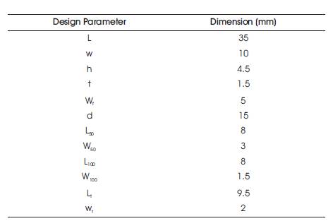
Table 1. Design Parameters
The performance of the array antenna is studied and found to be much improved as compared to a single element antenna. The return loss versus frequency plot is given in Figure 2. The array exhibits triband operation. The bandwidth at the first resonant frequency is considerably enhanced as compared to the single element antenna. Figure 3 shows the radiation pattern of the array. The performance comparison of single element and two element antenna is depicted in Table 2.
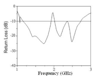
Figure 2. Return Loss vs. Frequency Plot of 2x1 Array of PILPA
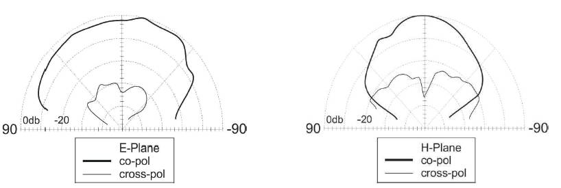
Figure 3. Radiation Patterns of 2x1 Array of PILPA

Table 2. Performance Comparison of 2 x 1 PILA
The 2x1 arrays of PILPA has been developed and their performance is being studied. The study shows that the array configurations present improvements in gain, impedance bandwidth, and the return loss characteristics apart from their compact and dual frequency operation. Hence it can be inferred that the antenna array structures show all the improvements in the performance characteristics of the antenna, but at the cost of increased size and complexity. Hence these antennas find application in the smart antenna system at base stations of mobile communication system and other wireless application.