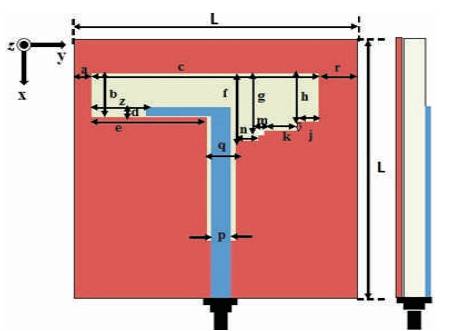
Figure 1. Structure of Proposed Antenna (Top View)
A compact UHF range RFID antenna with Circular Polarization (CP), which is proposed in this paper consists of stair shaped edge with irregular slots on one side and L-shaped feed line on the other. The L-shaped structure improves the Circular Polarization of antenna and provides CP mode at 2.68 GHz under UHF frequency range which is suitable for RFID applications. This antenna also provides bandwidth for RFID reader with -10 dB return loss (reflection coefficient) and have 3 dB axial ratio (AR < 3 dB) and impedance bandwidth (VSWR < 2) in the operating frequency band.
In the present era antenna design is a critical task, especially when improving various performance parameters like return loss, bandwidth, and gain. With emergence of wireless technology and increase in the demand for high-data-rate communication, compact size of antenna has become an important requirement for transferable applications [5, 6, 10]. Microstrip antenna are widely used for small portable equipment because of their compactness, low weight, low profile, and required ease of fabrication. Rectangular, circular, and triangular shape patch are commonly used patches. Though, changing the basic structure resulted to significant size reduction. In this work, the authors have designed RFID application based microstrip antenna for UHF frequency range. RFID technology associate to short-range wireless communication to read the certain devises known as tag. A RFID system having reader, reader antenna and tags; the communication happens between the RFID reader and the tag via reader antenna. Most of the UHF tag antennas are linearly polarized consequently circularly polarized UHF RFID reader antenna preferred in most of UHF RFID system which made epigrammatic handheld readers [4, 5]. Due to high data transfer rate and long readable range, generally UHF and SHF RFID antenna are preferred in many applications. In this work, the authors have designed for UHF RFID reader having one center frequency band between 2.45 GHz to 3 GHz. UHF RFID frequencies reader antenna is used for long range up to 12 meters.
The RFID system consisting reader antenna is a very important component regarding communication. It activates awakening the tag, transmit electromagnetic energy to tag, and send the instruction to tag. Generally, orientation of identified object is random and attaching tag to identify objects is also random and unfixed so that reader antenna should be circularly polarized.
Antenna gain and bandwidth is not a critical issue for RFID handheld devices, most importantly it has circular polarization and must cover one of the desired frequency bands for UHF RFID antenna [2]. Different structure has been proposed for designing of the antenna. Limited gain, small size, narrow impedance matching, and higher range must require circular polarization [3, 7- 9].
This paper presents a novel transmission system having circularly polarized microstrip antenna comprising of ground plane defected structure with stair type irregular slot, fed with 50 Ω microstrip line. The other side has Lshaped microstrip feed line. Staircase slots help to improve the circular polarization of the antenna [1].
The overall geometry and structure of the proposed antenna has been shown in Figure 1. The circularly polarized antenna has been designed on a FR4 substrate with dielectric constant of 4.4, loss tangent 0.02, and thickness of substrate is 1mm. The size of antenna is 52×52 mm2 designed at 2.68 GHz frequency in free space. The detailed dimensions of UHF RFID circularly polarized antenna are listed in Table 1.
Figure 1. Structure of Proposed Antenna (Top View)

Table 1. Proposed Structure Dimension
The proposed antenna irregular shape could optimize the circular polarization characteristic. In this paper, irregular slotted staircase is etched on ground plane and L-shape feed line etched on top of the plane.
Microstrip line has strip width of 3.5 mm and gap 0.75 mm between the strip and ground plane. The variation of 'z'& 'k' helps to optimize circular polarization.
The proposed irregular slotted defective ground structure was simulated to get improved results by changing the geometrical parameters. 3D simulator software was taken to demonstrate this antenna structure. The return loss (S11 parameter) of antenna is calculated which is shown in Figure 2. It is clearly shown in simulated results that antenna operates in UHF frequency band of RFID which is ranging from fL (= 2.42) GHz to fH (= 2.88 GHz). The calculated center frequency at 2.68 GHz for S has more than -10 dB return loss.
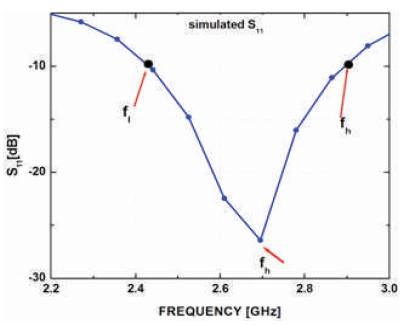
Figure 2. Simulated Result of Return Loss
The proposed antenna gives simulated impedance bandwidth (VSWR< 2) of about 17.35% (2.41 to 2.89 GHz) at 2.64 GHz center frequency shown in Figure 3. Figure 4 shows that the measured 3 dB axial ratio bandwidth is about 7.72% (2.49 to 2.69) at 2.59 GHz. It also clearly shows that AR bandwidth is within return loss bandwidth, i.e. it represents antenna operating in complete CP mode.
Figure 5 shows measured gain at boresight of antenna.The boresight reaches up to 5.2 dB with variation of less than 0.8 dBic.
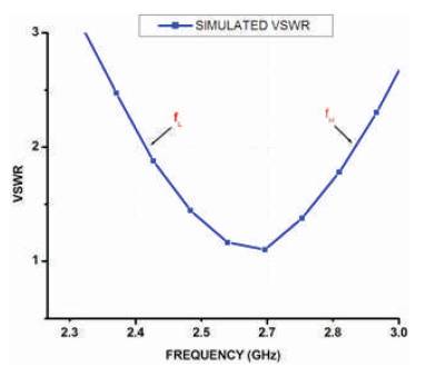
Figure 3. Simulated VSWR Result
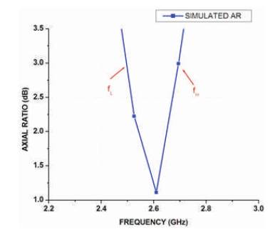
Figure 4. Simulated Result of Axial Ratio
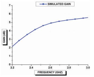
Figure 5. Simulated Result of Gain
The RHCP and LHCP radiation pattern are measured in XZ (Φ= 0o) and YZ plans (Φ= 90o) at the frequency of 2.68 GHz. Left Hand Circular Polarization (LHCP) is shown in Figure 6(a) and Right Hand Circular Polarization (RHCP) is illustrated in Figure 6(b) at frequency 2.44 GHz. The simulation result shows that the LHCP is better at Φ=0o, where as RHCP is better at Φ=90o.
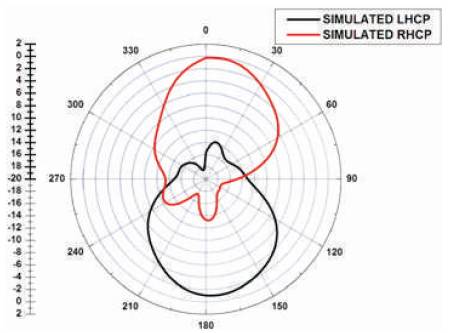
Figure 6(a). Simulated Result of Radiation Patterns in Azimuth Plane at Φ=0o
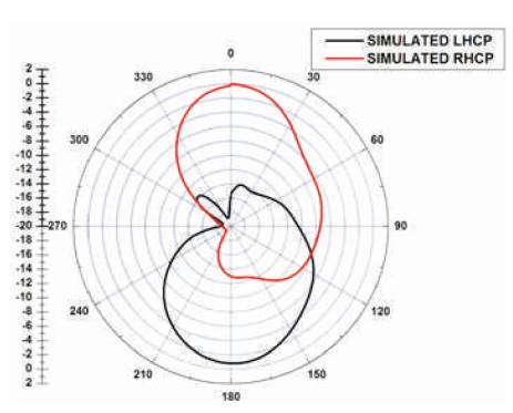
Figure 6(b). Simulated Result of Radiation Patterns in Elevation Plane at Φ=90o
In this paper, a novel circularly polarized slot antenna is proposed for 2.68 GHz RFID reader. The antenna is fed by stair-shaped line with irregular slot which would improve the circular polarization of antenna. It also has VSWR < 2 and AR < 3dB. The authors have demonstrated this antenna for handheld RFID reader applications. The antenna can cover at least RFID UHF frequency band. The antenna has wide angle circular polarization radiation. This proposed antenna is a compact and easy to find application as the reader antenna in handheld and portable RFID reader.