Figure 1. Basic Processor Architecture
In today's fast-paced technology industry, microprocessors play an increasingly important role in a wide range of applications. However, verifying the correctness of complex microprocessor designs remains a significant challenge. To address this issue, a rigorous approach to microprocessor verification using the Universal Verification Methodology (UVM) is proposed. UVM provides a standardised and scalable approach to verifying digital designs, including microprocessors, and has been widely adopted in the industry. This research proposes a UVM-based verification framework for microprocessors that can identify and eliminate design errors early in the development cycle. The proposed approach covers functional verification, performance verification, and hardware-software co-verification. The effectiveness of the proposed approach is evaluated through a case study of a commercial microprocessor design, where the UVM-based verification framework successfully detected and resolved several design bugs. The results demonstrate the potential of the proposed rigorous approach to microprocessor verification using UVM to enhance the quality and reliability of microprocessor designs.
The verification of complex microprocessor designs is a critical and challenging task in today's technology industry. With the growing demand for high-performance and reliable microprocessors, it is essential to ensure that these designs are free from errors and meet their intended specifications. The process of verifying a microprocessor design involves testing and validating its functionality, performance, and interactions with software and hardware components (Barbirotta et al., 2020). However, the complexity of modern microprocessors makes this process difficult, time-consuming, and error-prone. In recent years, Universal Verification Methodology (UVM) has emerged as a standardised and scalable approach to verifying digital designs, including microprocessors. UVM provides a framework for developing a comprehensive and efficient verification environment that can detect and eliminate design errors early in the development cycle. This research proposes a rigorous approach to microprocessor verification using UVM. The proposed approach covers functional verification, performance verification, and hardware-software coverification. The goal of this research is to develop a UVMbased verification framework for microprocessors that can enhance the quality and reliability of microprocessor designs. The effectiveness of the proposed approach is evaluated through a case study of a commercial microprocessor design. The results demonstrate the potential of the proposed rigorous approach to microprocessor verification using UVM to improve the overall quality and reliability of microprocessor designs.
Stotland et al. (2016) focus on functional verification of communication controllers based on developing layered UVM test systems is considered in this paper. Some benefits of application-standalone simulationbased verification are marked out. The communication controllers typically comprise three logical layers: the transport layer, the channel layer, and the physical layer, each serving distinct functions. This paper outlines the key features and functionalities of each of these layers.
To efficiently test the communication controllers, we propose developing a Unified Verification Methodology (UVM) test system and a Design Under Test (DUT) that includes controllers for each of the three layers.
Sharma et al. (2022) show a composite UVM-SystemC methodology to rationally adhere to optimal test path selection among all test paths. The work presents the SCUVM (System C-UVM) architecture for cross-platform working facilitation. The learning methodology works to improvise coverage parameters with the optimization of coverage bins. By reducing internal data processing and simulation time, the methodology makes a significant contribution to early verification. The System C-UVM method outperforms the conventional systemverilog and sole UVM verification technique.
Liew (2022) says that for processors with advanced microarchitectural features implemented, a simulationbased approach is taken for their functional verification. More specifically, the Universal Verification Methodology (UVM) is utilised for the verification methodology of the RISC-V processor implementation in this report. UVM provides a set of guidelines for the verification test benches to be generated. With a well-defined testbench structure, UVM allows for a standardised approach to verification work and the verification of systems to be performed consistently and uniformly, greatly improving the quality of verification and the reusability of testbenches. For the verification approach, constrained random verification and direct verification approaches will be taken to verify the functionality of the RISC-V processor.
Qamar et al. (2020) summarise the latest advancements, tools, and techniques for the UVM standard. Therefore, this article performs a Systematic Literature Review (SLR) to identify 27 studies (i.e., 2017–2019) pertaining to the UVM standard. Subsequently, 21 UVM-based frameworks and nine tools are identified. Moreover, key benefits of the UVM standard are investigated. Finally, a comparative analysis of UVM with Open Verification Methodology (OVM) is performed. It is concluded that UVM provides advanced phasing mechanisms, reporting, callbacks, objections, sequence libraries, and control over simulation as compared to OVM.
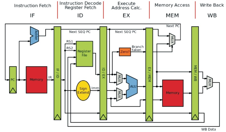
The approach involves a comprehensive process of verifying the design to ensure that it meets its functional requirements and operates correctly. The methodology consists of several steps, beginning with a clear problem statement and motivation for the study. This is followed by a literature review to identify the concepts and best practices used for microprocessor verification and UVM. Based on the literature review, a rigorous methodology is developed for microprocessor verification using UVM (Fathy & Salah, 2016). This involves identifying the different UVM components to be used, such as sequences, drivers, monitors, and scoreboards. Modifications or adaptations to the UVM methodology to suit the specific needs of the work are also outlined. Once the methodology is implemented on a microprocessor design, the design is tested and verified using UVM (Mahmoud et al., 2022). The implementation includes setting up the simulation environment, developing test benches and test cases, and running simulations to test the design. Figure 1 illustrates the basic processor architecture.
Figure 1. Basic Processor Architecture
The basic processor architecture for Universal Verification Methodology (UVM) refers to the fundamental structure of the processor that serves as the foundation for the verification environment. The architecture consists of several modules, including a processor core, memory subsystem, and various interfaces (Sharma et al., 2022). The processor core is the Central Processing Unit (CPU) of the microprocessor design, which performs the arithmetic and logic operations required by the Instruction Set Architecture (ISA). It also contains control logic that manages the execution of instructions and the control flow of the processor. The processor core is responsible for executing the instructions and generating the output results. The memory subsystem includes various types of memory, such as cache, Random Access Memory (RAM), and Read Only Memory (ROM) that are used for storing data and instructions during processor operation. It also includes memory controllers that interface with the processor core to provide access to memory (Salah, 2017).
The processor architecture also includes various interfaces that enable the processor to communicate with other components in the system (Stotland et al., 2016). These interfaces include bus interfaces, input/output (I/O) interfaces, and peripheral interfaces. Bus interfaces enable communication between the processor and other components in the system, such as memory and I/O devices. I/O interfaces enable communication between the processor and external devices, such as keyboards, displays, and other peripherals (Herdt et al., 2020). Peripheral interfaces enable communication between the processor and other system components, such as sensors and actuators. The basic processor architecture for UVM serves as a reference model for developing test benches and test cases in the verification environment. The architecture provides a guide for defining the stimuli and expected results for the different components and interfaces of the processor. By using a reference model, the verification process can be made more efficient and effective, ensuring that the processor design is thoroughly and accurately tested.
The comparison between traditional testing and UVM is shown in Table 1. Traditional testing is often ad-hoc and less reusable, as new tests need to be developed for each new design. UVM provides advanced debugging features, such as transaction-level debugging, which allows designers to identify and resolve errors more quickly and efficiently (Qamar et al., 2020). UVM offers advanced debugging features, including transaction-level debugging, that enable designers to identify and resolve errors quickly and efficiently. UVM provides a more comprehensive and systematic approach to microprocessor verification, with advanced features that make the verification process more efficient and effective.
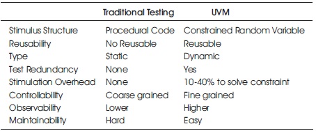
Table 1. Comparison between Methodologies
The paper should start with a clear problem statement, highlighting the need for rigorous verification of microprocessors to ensure their correct functioning. The motivation for the study should also be presented, emphasizing the importance of reliable microprocessors and the challenges involved in verifying complex designs. Based on the literature review, a rigorous methodology for microprocessor verification using UVM should be developed, which includes identifying the different UVM components such as sequences, drivers, monitors, and scoreboards. Any modifications or adaptations to the UVM methodology to meet the specific needs of the project should also be outlined.
The problem statement underlines the criticality of microprocessors and their importance in various applications (Jones et al., 2001). As microprocessors have become more complex, verifying their correctness has become increasingly challenging. Traditional verification methods such as simulation and testing are inadequate to ensure that the design meets its functional requirements (Mehta, 2018). A more systematic and rigorous approach to verification, such as the Universal Verification Methodology (UVM), is necessary to address this issue. The aim of this paper is to present a more robust and reliable approach to verify microprocessor designs to ensure their correct functioning and to prevent any potential consequences of design errors.
Any flaws or errors in the microprocessor design can lead to unexpected behavior or even catastrophic consequences, such as system crashes or security breaches.
The motivation for a rigorous approach to microprocessor verification using Universal Verification Methodology (UVM) is to ensure that microprocessors are designed correctly and can perform their intended functions reliably. The conventional method of microprocessor verification entails testing each instruction in isolation, which can be tedious, prone to errors, and inadequate in terms of testing all potential scenarios (Tieth & Menghal, 2022). A rigorous approach using UVM can help address these challenges by providing a standardized and efficient way of verifying the microprocessor's design.
The security requirements specify any security features or mechanisms required to protect the microprocessor from unauthorized access or attacks. Defining the microprocessor's functional requirements and specifications is a critical step in the design process, as it lays the foundation for the rest of the design process. It helps ensure that the microprocessor is designed to meet the intended use cases and performance requirements, as well as any other constraints or limitations that may be relevant to the design. Confidentiality, integrity, and availability are the three main security policy goals.
To develop a detailed microprocessor design, including the architecture, instruction set, and register set, you can write test cases to verify the microprocessor's correctness and ensure it meets the functional requirements and specifications. The detailed microprocessor design flow diagram is shown in Figure 2.
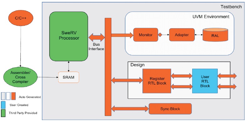
Figure 2. Detailed Microprocessor Design
The microprocessor design is based on a Harvard architecture, which means that it has separate instruction and data memory spaces. The microprocessor has a 32- bit address bus and a 32-bit data bus. The Instruction Set includes loading an immediate value to a register, loading a value from memory to a register, storing a value from a register to memory, adding two registers and storing the result in a register, subtracting two registers and storing the result in a register, jumping to a memory address, jumping to a memory address if a certain condition is met, and branching to a memory address relative to the current program counter value. The microprocessor has 16 general-purpose registers named R0 to R15. It also has a Program Counter (PC) register and a Status Register (SR). The status register has the flags namely carry, zero, negative, and overflow.
To verify the functionality of the microprocessor, a UVM test bench can be developed that generates stimulus and checks the output of the microprocessor for correctness (Loh et al., 2022). The test bench can include a sequence of instructions that exercise the different functionalities of the microprocessor, such as loading and storing values from memor y, performing arithmetic and logic operations, and branching and jumping to different parts of the program. The output of the microprocessor can be checked using UVM assertions to ensure that it matches the expected results.
Develop a UVM-based test bench to automate the testing process, including stimulus generation and response checking. Figure 3 shows the UVM test bench.
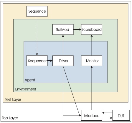
Figure 3. UVM Test bench Hierarchy
A Universal Verification Methodology (UVM)-based test bench is a methodology for developing and running verification tests for digital designs. The testbench is written in SystemVerilog, and it uses the UVM library to create a standardised methodology for verification (Yun et al., 2011). The UVM-based testbench is composed of several modules that work together to create a complete verification environment (Warke, 2018). These modules include the test, the environment, the sequence, the driver, the monitor, and the scoreboard. The test module defines the stimulus that will be applied to the design being tested. It contains a sequence of commands that are sent to the Design Under Test (DUT) through the environment module. The environment module provides the interface between the test module and the DUT. It contains the necessary components, such as drivers, monitors, and scoreboards, that are required to communicate with the DUT. The sequence module defines a sequence of transactions that are sent to the DUT. The transactions are created by the test module and sent to the driver through the sequence module. The driver module converts the transaction sequences created by the sequence module into signal-level data that can be applied to the DUT. It contains the necessary logic to interface with the DUT, such as clock gating and synchronization. The monitor module observes the signals coming from the DUT and converts them into transactionlevel data that can be analysed by the scoreboard. The monitor is responsible for collecting data such as input/output ports and status signals of the DUT.
The scoreboard module compares the expected results generated by the test module with the actual results generated by the DUT. If there is a mismatch, the scoreboard will generate an error message to indicate that the DUT has failed the test. The UVM-based testbench uses a layered, hierarchical approach to verification. This allows the designer to build a modular verification environment that can be reused and extended for future designs. The UVM-based testbench also provides a standardised methodology for verification, which makes it easier for verification teams to collaborate and share code. The UVM-based test bench is a powerful tool for digital design verification (Chen et al., 2021). It provides a standardised methodology for verification that can be reused across multiple designs, and it allows designers to create a modular verification environment that can be extended for future designs.
Verify the microprocessor's design using the UVM-based test bench and debug any errors or issues that are found. To verify the microprocessor's design, we can use a UVMbased test bench that applies different input stimuli to the microprocessor and checks the output produced by the microprocessor against expected results. The test module generates the test cases that will be applied to the microprocessor. It sends a sequence of instructions to the microprocessor and verifies the output produced by the microprocessor. The test module also generates the expected results for each test case. The environment module inter faces the test module with the microprocessor. It contains the necessary components, such as the driver, monitor, and scoreboard, to communicate with the microprocessor. The sequence module generates the instruction sequences that are sent to the microprocessor by the driver. The instruction sequences can include load, store, arithmetic, logic, and branch/jump instructions. The driver module converts the instruction sequences generated by the sequence module into signals that can be applied to the microprocessor. It interfaces with the microprocessor's bus interface and ensures that the instructions are applied at the correct time and with the correct data values. Figure 4 shows the UVM verification components in the microprocessor's design.
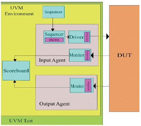
Figure 4. UVM Verification Components
The monitor module observes the signals produced by the microprocessor and generates transaction-level data that can be analyzed by the scoreboard. It collects data such as the contents of the microprocessor's registers and the status of the microprocessor's flags. The scoreboard module compares the expected results generated by the test module with the actual results produced by the microprocessor. If there is a mismatch, the scoreboard will generate an error message to indicate that the microprocessor has failed the test. The UVM-based test bench can be run using a simulator that supports System Verilog and the UVM library. During the simulation, the test module generates the test cases, and the environment module interfaces with the microprocessor to apply the instructions and collect the results. The monitor module observes the signals produced by the microprocessor, and the scoreboard module compares the expected results with the actual results. If the microprocessor passes all the tests on the UVM-based test bench, then we can conclude that the microprocessor's design is correct and meets the specifications. If the microprocessor fails any of the tests, then we need to investigate the cause of the failure and modify the design accordingly.
Repeat the verification process until the microprocessor design meets all functional requirements and specifications. A rigorous approach to microprocessor verification using UVM can help ensure that microprocessors are designed correctly and can perform their intended functions reliably (Yun et al., 2011). It provides a standardised and efficient way of verifying the microprocessor's design, allowing for faster time-tomarket and reducing the risk of errors or failures. Create a new UVM-based testbench for the microprocessor's design. This test bench should be similar to the one created earlier, but with updated test cases and expected results based on any changes made to the microprocessor's design. Run the simulation using a simulator that supports system verilog and UVM.
Monitor the simulation to ensure that the microprocessor is operating correctly and producing the expected results. Analyze the results produced by the scoreboard module to ensure that the microprocessor has passed all the tests on the test bench. If the microprocessor has failed any tests, investigate the cause of the failure and modify the design accordingly. Repeat the simulation and verification process until the microprocessor passes all the tests on the test bench. Once the microprocessor has passed all the tests, we can conclude that the design is correct and meets the specifications. It's important to note that the verification process should be repeated whenever changes are made to the microprocessor's design. This ensures that the design remains correct and meets the specifications, even as it undergoes changes during the design process. The UVM-based testbench provides a standardised methodology for verification, making it easier to repeat the verification process and maintain the integrity of the microprocessor's design (Hasan & Tahar, 2015).
The methodology should be implemented on a microprocessor design, and the design should be tested and verified using UVM. The implementation should be described in detail, including the simulation environment, test benches, and test cases used. UVM is a widely used verification methodology for testing digital designs, including microprocessor designs. It provides a standardised framework for creating test benches and test cases, which can help ensure that a design is functioning correctly. In order to use UVM to verify a microprocessor design, you would typically create a UVM testbench that interfaces with the microprocessor design in the simulation environment. The test bench would generate input values for the microprocessor design and then monitor the output of the design to ensure that it behaves correctly. Implementation of microprocessor design in the UVM is shown in Figure 5.
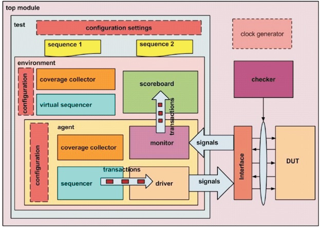
Figure 5. Implementation of Microprocessor Design in UVM
During simulation, the test bench would log various information, including the results of the tests that were run. This information would be stored in data files or databases, which could be used to analyse the test results. If you're asking about how to analyse the data results from a UVM-based verification environment, there are several tools and techniques that can be used. For example, you could use waveform viewers to visualise the signals in the design and see how they change over time. You could also use coverage analysis tools to see how much of the design has been exercised by the tests. UVM can be used to verify a microprocessor design in the simulation environment, and the results of the verification can be analysed using a variety of tools and techniques.
The results obtained from the verification process should be analyzed and presented clearly and concisely. The effectiveness of the UVM methodology in identifying design errors and ensuring that microprocessor meets its functional requirements should be evaluated.
The results obtained from the verification process of the microprocessor design in Universal Verification Methodology (UVM) would include information about the design's performance and correctness, as well as any issues encountered during the verification process. Here are some of the typical results that can be obtained from the UVM-based verification process:
UVM provides a coverage-driven verification methodology, which means that coverage metrics can be collected during the simulation to determine the percentage of the design that has been exercised by the testbench. The coverage metrics can be used to identify areas of the design that have not been fully tested, and additional test cases can be added to improve the coverage.
Coverage results are an important part of the verification process of a microprocessor design in Universal Verification Methodology (UVM). Coverage metrics can be collected during the simulation to determine the percentage of the design that has been exercised by the testbench. This helps identify areas of the design that have not been fully tested, and additional test cases can be added to improve the coverage. The coverage results can be divided into two main categories namely functional coverage and code coverage. Functional coverage metrics track the number of functionalality scenarios that have been exercised during the simulation. These metrics can be defined in the test plan and are used to ensure that all the functionality scenarios have been covered. For example, functional coverage can track the number of times each instruction in the instruction set has been executed, or the number of times each register in the register set has been written to or read from. Code coverage metrics track the number of lines of code that have been executed during the simulation. This metric is used to ensure that all the lines of code in the microprocessor design have been executed at least once. Code coverage can be further divided into various types of coverage, such as statement coverage, branch coverage, or condition coverage. The coverage results are typically presented in a coverage report that shows the coverage metrics for each coverage point defined in the test plan. The report can be used to identify the areas of the design that have not been fully covered and to guide the development of additional test cases to improve the coverage. In summary, coverage results are an important part of the verification process of a microprocessor design in UVM, and they provide a measure of the completeness and efficacy of the testbench. High coverage results indicate that the design has been thoroughly tested, while low coverage results indicate that additional testing is required to ensure the design's correctness and completeness.
Assertions can be added to the UVM-based testbench to check the correctness of the microprocessor's behavior. Assertion results can be used to identify errors in the design, such as invalid state transitions or incorrect outputs. Assertion results are an important aspect of the verification process of a microprocessor design in Universal Verification Methodology (UVM). Assertions are statements that check the correctness of the microprocessor's behavior by comparing expected results to actual results during the simulation. Assertionbased verification is a powerful technique for identifying design errors and can detect problems that are difficult to find with other verification methods.
UVM provides a rich set of assertion constructs that can be used to express complex design properties. The assertion constructs can be used to check the correctness of the microprocessor's behavior at various levels of abstraction, including register transfer level (RTL) and transaction level. During the simulation, if an assertion fails, it indicates that the design has violated a design property, and an error message is generated. The error message provides information about the assertion that failed, the values of the signals or registers at the time of the failure, and the simulation time at which the failure occurred. This information can be used to quickly identify and debug the problem. Assertion results can be used to identify a wide range of design issues, including invalid state transitions, incorrect data path operations, timing violations, and interface errors. By using assertions, it is possible to find problems in the design that might be difficult or impossible to detect with other verification methods. Assertion results are an important part of the verification process of a microprocessor design in UVM. By checking the correctness of the design using assertions, it is possible to identify and debug design errors quickly and effectively. Assertion-based verification is a powerful technique that complements other verification methods and can help ensure the correctness and robustness of the microprocessor design.
The simulation results can be used to determine the microprocessor's performance, such as its execution time or throughput. Performance results can be used to identify bottlenecks in the design or opportunities for optimization. The performance results typically refer to metrics that are used to measure the effectiveness and efficiency of the verification process. UVM is a widely used verification methodology in the semiconductor industry that helps ensure that a microprocessor design is functionally correct and meets the specified requirements. Code coverage metric measures the extent to which the verification environment has exercised the code under test. The higher the coverage, the more confident you can be that the design has been thoroughly tested. Functional coverage measures the completeness of the verification environment's testing of the design's functionality. Functional coverage is typically measured in terms of the percentage of functional coverage points that have been hit during the verification process. Simulation time is the total time required to simulate the design using the verification environment. Reducing simulation time can help speed up the verification process and improve overall efficiency.
Memory usage is the amount of memory required to simulate the design using the verification environment. Managing memory usage effectively can help prevent simulation crashes or slowdowns. Bug discovery rate measures the rate at which bugs are discovered and fixed during the verification process. A high bug discovery rate can indicate a high level of quality and thoroughness in the verification process. By tracking and analyzing these performance results, verification engineers can gain insights into the effectiveness and efficiency of their verification process and make improvements as needed to ensure that the design meets its functional requirements.
The UVM-based testbench provides detailed debugging information, such as the values of signals and registers at various points in the simulation. This information can be used to identify the cause of any errors encountered during the verification process. Debugging information is typically stored in a separate file or section of the executable or library rather than being included directly in the main binary file. This allows the debugging information to be stripped from the final release version of the software, reducing its size and improving its performance. Debugging information can be accessed using a debugger, a specialised tool that allows developers to examine and modify the state of a programme as it is running. By using a debugger to step through a program's execution and examine its memory and variables, developers can diagnose and fix bugs in the software more quickly and effectively.
The verification process will produce pass/fail results for each test case on the test bench. If the microprocessor passes all the test cases, then the design can be considered verified. If the microprocessor fails any of the test cases, then the issues will need to be identified and resolved before the design can be considered verified. In microprocessor verification using UVM, pass/fail results refer to the outcome of running a test case against the microprocessor design being verified. A pass result means that the test case was executed successfully and the microprocessor design met the expected behaviour specified in the test case. A fail result means that the test case did not execute successfully or that the microprocessor design did not meet the expected behaviour specified in the test case. The pass/fail results are typically generated by the UVM test bench and reported to the verification engineer through a test report. The test report provides a summary of the pass/fail results for each test case and may include additional details such as the simulation time, coverage metrics, and debug information to help the verification engineer analyse and diagnose the cause of any failures. The pass/fail results are a critical aspect of the microprocessor verification process, as they provide a measure of the quality of the design and the effectiveness of the test bench in verifying the design's functionality. A high pass rate indicates that the design is meeting the specified requirements and that the test bench is effective in detecting bugs. A low pass rate, on the other hand, indicates that there may be issues with the design or the test bench that need to be addressed. By using the pass/fail results to guide their efforts, verification engineers can help ensure that the microprocessor design is thoroughly tested and meets its functional requirements. Overall, the results obtained from the verification process in UVM provide insight into the design's correctness, completeness, and performance. These results can be used to make decisions about the design's suitability for its intended purpose and to identify areas for further optimization or improvement.
Developing a rigorous methodology for microprocessor verification using UVM is an essential aspect of microprocessor design process. One of the key challenges in developing a rigorous methodology for microprocessor verification is ensuring that the verification plan covers all the functional requirements of the design. This requires a deep understanding of the microprocessor architecture and how it is intended to be used. The verification engineer must work closely with the design team to ensure that the verification plan covers all the important aspects of the design and that it is comprehensive and effective. This requires expertise in UVM methodology and the ability to develop test cases that effectively verify the microprocessor design. The verification engineer must also ensure that the testbench is scalable and maintainable, as the size and complexity of the design can grow rapidly over time. The verification engineer must be able to interpret the results of each test case and diagnose any issues or bugs in the design or test bench. This requires strong analytical skills and a deep understanding of the microprocessor architecture and how it is intended to be used. Developing a rigorous methodology for microprocessor verification using UVM requires a deep understanding of the microprocessor architecture, strong analytical skills, and expertise in UVM methodology. By following a structured approach, verification engineers can ensure that the microprocessor design meets its functional requirements and performs as expected, which can help reduce the risk of costly bugs and improve the quality of the final product.
A rigorous methodology for microprocessor verification using Universal Verification Methodology (UVM) is crucial to ensure that the microprocessor design meets its functional requirements and performs as expected. This methodology helps to identify bugs early in the development process, saving significant time and resources. To implement the UVM testbench, maximum coverage of the design should be achieved to ensure that all functional requirements are tested. The verification plan is executed to test the microprocessor design, and the results of each test case are analyzed to determine whether the design meets the expected behavior. Continuous monitoring and improvement of the methodology are necessar y to maintain effectiveness over time, including analysing performance results such as code coverage, functional coverage, simulation time, and memory usage.