(1)

This article compares the accuracy achieved by the various Resistance Temperature Detector (RTD) configurations using the MAX31865 device. This design offers an interface for PT100 RTD using MAX31865 RTD to digital converter. The RTD is connected to the anti-aliasing filter and the filter output is converted into a digital signal using the MAX31865 device. The final temperature readout is monitored on the computer for validation. The proposed temperature sensor interfacing can be utilized in multi-channel temperature measurement in the telemetry systems. RTD sensor configurations with 2, 3 and 4 wires are evaluated and accurate results are obtained in 4 wire configuration. Furthermore, in this sensor interfacing Serial Peripheral Interface (SPI) output requires only one micro-controller unit, which reduces the circuit complexity and power requirement to a great extent.
There are various sensors to measure the temperature like, Thermocouple, Resistance Temperature Detectors (RTDs), an Infrared sensor, Bimetallic devices, Thermometer, and Silicon diodes are a few of them. There have been various methods discussed in the past by the researchers for the measurement of the temperature (Campbell, 1970; Makinwa & Witte, 2005; Liu, Li, & Zhao, 2010; Van- Vroonhoven & Makinwa, 2011). In Makinwa and Witte (2005), the authors have used the thermal diffusion coefficient of the silicon for the measurement of the temperature. It uses the frequency-locked loop in which the thermal filter determines the frequency of oscillation and they use this frequency as a measure of temperature. This method is suitable for over the temperature range of −50°C to 125°C. By measuring the temperature dependent thermal diffusivity of silicon a temperature sensor is presented in the previous literatures (Liu, et al., 2010; Van-Vroonhoven & Makinwa, 2011; Quan, Sonmez, Sebastiano, & Makinwa, 2015). A temperature dependent electro thermal filter based on thermal diffusivity of bulk silicon is being used to measure the temperature by measuring the phase shift of the filter (Kashmiri, Xia, & Makinwa, 2009; Kashmiri, Pertijs, & Makinwa, 2010). Liu et al. (2010), have used an Analog to Digital Converter (ADC) device to interface the temperature sensor with the micro-controller unit. The device also provides signal conditioning and constant current source to the RTD sensor. In Sönmez, Sebastiano, & Makinwa, 2016 and Zhu, Liu, Yang, & Yan, 2015, the temperature measurement system was developed using the principle of the thermocouple. The thermocouple was interfaced using a micro-controller chip and an ADC and the final output is demonstrated in a software platform. Wireless temperature sensors are also being studied by the researchers to describe the mobile temperature data logger (Sveda, Benes, Vrba, & Zezulka, 2005). The CMOS based sensors are proposed in various literatures (Huang et al., 2014; Lee, Hsu, & Luo, 2006; Salem et al., 2006). In recent years, RTDs have been used extensively for the measurement of temperature because they give an accurate and stable readout.
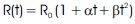
All RTDs are based on the principle that the electrical resistivity of the metal changes with the temperature. The electrical resistance of some materials such as platinum, copper, and nickel differs at different temperatures. RTDs take advantage of this property to assess temperature in a variety of commercial and industrial applications. The relation between temperature and resistance of the material is defined by equation (1).
Here R0 is the resistance at 0°C of the PT100 RTD, R(t) is the resistance at t°C and α, β, etc. are the temperature coefficients.
The temperature coefficient α, and β of RTD is the physical and electrical property of the element, which depends upon the material and the method by which the element was manufactured. The material gives a stable temperature reading if higher order terms of temperature are zero (Campbell, 1970). The resistive element of the RTD plays a crucial role in the temperature measurement. Therefore, it is necessary to select the RTD material correctly to obtain the accurate result.
MAX31865 is interfaced with the computer system that works as a data acquisition system while resistance is varied with the help of resistance simulator as shown in Figure 1.
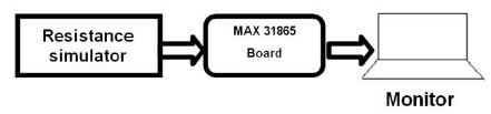
Figure 1. Block Diagram of the Test Setup
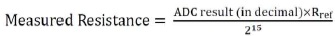
To measure the RTD's resistance, connect a Reference Resistor (RREF) and RTD in series and apply the bias voltage to the top of RREF. The reference resistor current flows REF through the RTD. The voltage across the reference resistor is the reference voltage for the ADC. The voltage across the RTD is applied to the ADC's differential inputs (RTDIN+ and RTDIN-). The ADC therefore produces a digital output that is equal to the ratio of the RTD resistance to the reference resistance. A reference resistor equal to four times the RTD's 0°C resistance is optimum for a platinum RTD. Therefore, a 400Ω reference resistor is used in this case.
First the Resistance of the RTD needs to be determined. Once the resistance of the RTD is known, the well-defined resistive properties of the selected RTD can be used to determine temperature by either calculations or lookup tables.
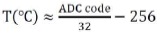
The MAX31865 is a RTD to digital converter, which has in built 15- bit Analog to Digital converter (Maxim, 2015). It has an SPI compatible interface, a digital controller and over input voltage protection circuit. The MAX31865 device can be used to work with PT100 through PT1000 RTDs. The temperature conversion formula with -1.75 error at -100 and -1.4 error at 100 is given by (3).
Sensors other than RTD may be used in conjunction with MAX31865. In that case, reference resistance must be equal to or greater than the maximum resistance of the sensor over the required temperature range. The measured temperature is given by the ratio of the sensor resistance to the reference resistance. The MAX31865 has Sigma-Delta ADC with sinc filter which results in more accurate measurements as compared to SAR (Successive Approximation Resistor) ADC.
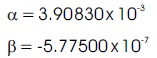
PT100 RTD is a positive temperature coefficient sensor which offers great accuracy over a temperature range of -200°C to +850°C. These are highly linear over the temperature range of -40°C to + 80°C. PT100 RTD provides the highly accurate result and upto ±1°C accuracy can be achieved using it. The resistance temperature relation for PT100 may be approximated as,
The Callendar-Van Dusen coefficient values are as follows:
Noise is the unwanted signal which interferes with the desired signal. The presence of noise degrades the performance of the electronic system. According to the conduction mode noise is of two types:
To manage the channel noise, filters or smoothing circuits are required. Therefore, to eliminate common mode and differential mode noise from the channel an LC filter is connected to the RTD sensor as shown in Figure 2.
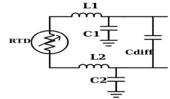
Figure 2. LC Filter Circuit for Noise Elimination
The cutoff frequency of the LC filter can be calculated as
The values of the components of the LC filter depend upon the signal of interest. Cdiff is the differential capacitor diff which caters any mismatch due to common mode capacitor C1 and C2.
3.1 2-Wire Configuration
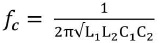
The 2- Wire configuration is the fundamental configuration. In this configuration two wires are used to connect the sensors. The resistance of the connecting wire gets added to that of the resistance of RTD sensor which results in an error in the measurement. Long wires contribute more resistance and hence may result in a severe error in the final readout of the temperature. Therefore, two wire configurations are not suitable for the applications where accuracy is the main concern or the sensors are placed at a long distance from the transmitter. Figure 3 shows the connection diagram for 2-wire configurations using MAX 31865.
Figure 3. Connection Diagram for 2-Wire configuration of RTD Sensor
The value of the capacitor C1* depends upon the resistance value of the RTD. For the PT100 RTD C1*=100 nF.
The FORCE+ and FORCE- pin are shorted with RTD+ and RTD- pin respectively. The RTD is connected between RTD+ and RTD- pin with the help of two wires.
For the experiment, the authors have used a 22 AWG wire of length 2.2 meters, which has a resistance of 0.116 . Table 1 shows the measurement for the 2-wire configuration.
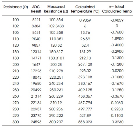
Table 1. Temperature Measurement using 2-Wire RTD Configuration
In 2-wire configurations, an error ( ) caused by the wire resistance can be calculated as

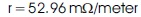
Where L is the length of the wire, r is the resistance per unit length and S is the sensitivity. For PT100 RTD, sensitivity is given by,
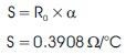
For 22 AWG wire resistance per unit length is
Putting all the values in (4)

The error is small in this case because the sensor is placed near to the device, but this error increases as the length of the wire increases. The error caused by the lead resistance can be compensated by using the 3-wire configuration.
The calculated temperature is plotted against the resistance for PT100 RTD as shown in the Figure 4. There is a considerable difference between the ideal temperature and the calculated temperature from the temperature range of 106°C to 109°C for the 2-wire configuration. The difference between the ideal temperature and the calculated temperature gets increased as the resistance increases.
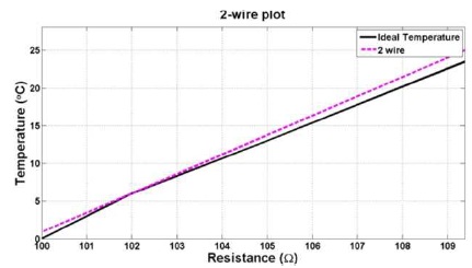
Figure 4. Resistance Versus Temperature Plot for the 2-Wire configurations
3.2 3-Wire Configuration
In 3-wire RTD configuration shown in Figure 5, there is a third wire which compensates the lead wire resistance, third wire gives the value of the resistance of the wire and by subtracting this resistance value from the measured resistance value of the wire accurate results are obtained. Therefore, 3-wire RTD configuration provides better accuracy than the 2-wire configuration. It minimizes the error caused by the wire resistance.
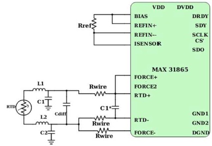
Figure 5. Connection Diagram for 3-Wire Configuration of RTD Sensor
The FORCE+ pin is shorted with the RTD+ pin and the RTD is connected between RTD+ and RTD- pin while the third wire is connected to the FORCE- pin.
In this configuration, three wires of equal length are used to connect the RTD with the MAX31865 device. Table 2 shows the temperature measured using the 3-wire configuration. The precision achieved in this configuration is more than the 2-wire configuration.
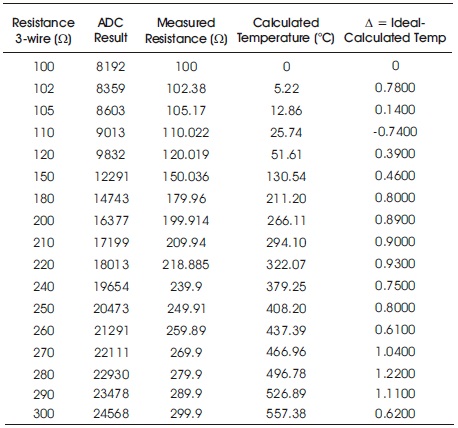
Table 2. Temperature Measurement using 3-Wire RTD Configuration
The difference between ideal temperature and the calculated temperature for 3-wire RTD configuration for the resistance ranging from 100 to 109 is depicted in Figure 6. Though there is a visible deviation of the calculated temperature from the ideal temperature, it is less as compared to 2-wire RTD configuration.
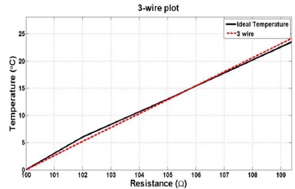
Figure 6. Resistance Versus Temperature Plot for the 3-Wire Configuration
3.3 4-Wire Configuration
The third type of RTD wiring configuration is 4-wire RTD in which resistance of 4-wire cancel out each other and compensate the error caused by the wire resistance. The resistance error caused by the wire is zero in this configuration. The 4-wire configuration provides accurate and precise temperature readings.
Figure 7 shows the connection diagram for the 4- wire configuration, here 4 wire are used to connect the RTD to the MAX31865 device.
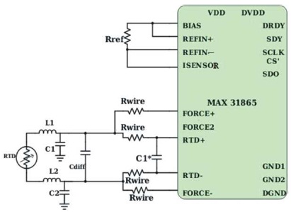
Figure 7. Connection Diagram for 4-Wire Configuration of RTD Sensor
RTD sensor is connected between RTD+ and RTD- pin and the third and fourth wire are attached to the FORCE+ and FORCE- pin.
Figure 8 shows the plot for the calculated temperature and the resistance for 4-wire RTD configuration. The calculated temperature coincides with the ideal temperature for most of the resistance values. Therefore, the 4-wire configurations offer the most accurate temperature value as compared to the other two configurations.
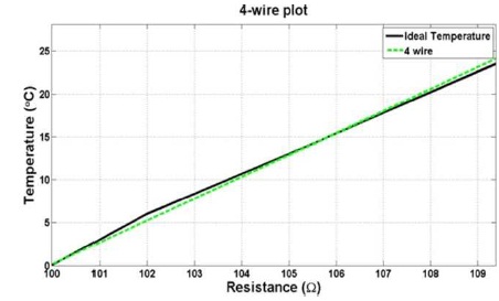
Figure 8. Connection Diagram for 4-Wire Configuration of RTD Sensor
The 2-wire configuration is the least precise of the three configurations and it can be used when the accuracy is not the main concern. The 3-wire RTD configuration provides satisfactory results and it is widely used in the industrial applications. The 4-wire provides the most accurate result and generally, it is preferred in calibration and laboratory applications.
The parameter ∆ shows deviation of calculated temperature from the ideal temperature. For the 2- wire configuration ∆ is negative for most of the readout as shown in Table 1. The smaller ∆ value indicates more accurate read value. Its value decreases as the number of wire increases. As it is clear from the Table 2 and Table 3 the decreases excluding few readings.
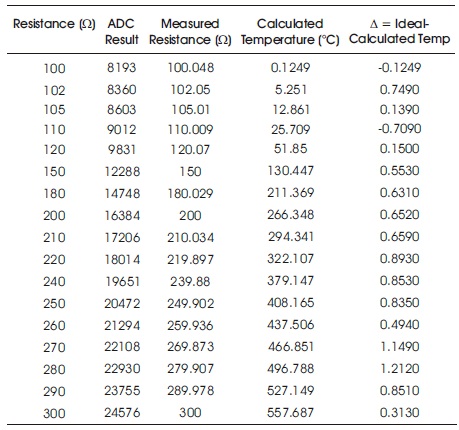
Table 3. Temperature Measurement using 4 Wire RTD Configuration
The selection of the wiring configuration of the RTD depends upon the requirements of the customer. The 2- wire configuration is generally preferred where the sensor is located nearer to the measurement instrument and wire length is short. A 2-wire connection can give acceptable results when the RTD is located close to the MAX31865. For a PT100, series resistance of 0.4 causes an error of approximately 1°C. Therefore, as the cable length increases, the error due to cable resistance can become excessive. In future, the authors plan to test the model for multi channel temperature sensor.