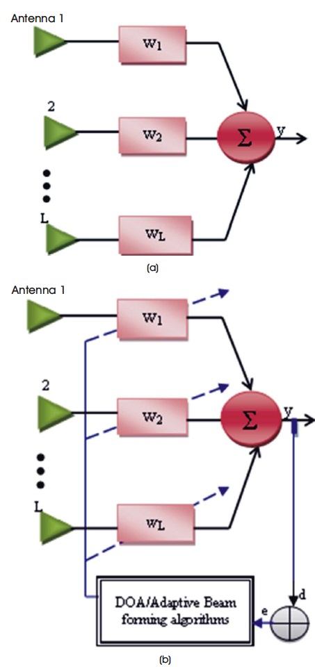
Figure 1. (a) Traditional Antenna Array (b) Smart or Adaptive Antenna
A smart antenna system attracts a lot of attention now a days and believed to be more in the future. The smart antennas when used in communication system, enhances the system capacity, efficiency and bandwidth. From the past decade huge amount of research has been carried out in array signal processing to improve the communications systems. In this paper, most popular beamforming methods used in array signal processing are discussed in terms of its benefits and the reason for its popularity. Furthermore, various fixed weight beamforming and adaptive beamforming techniques are also discussed in this paper. A simulation of beamforming in a particular direction of interest with nulls in interfering o o directions is done using MATLAB simulation software. Array factor for the range between -90o ≤ θ ≤ 90o are plotted The purpose of this article is to give an overview of the technology and used beamforming techniques.
In recent years, smart antenna for mobile communication has received enormous interest worldwide. From the last 10 years wireless communication has significantly attained the drastic growth to meet the demands of today's requirement, particularly in cellular communication. This is possible by the use of multiple antennas at the transmitter and/or receiver. These antennas are also called as adaptive or smart antennas (Godara, 1997; Kwong & Johnston, 1992).
The adaptive antennas can be employed to increase the reliability in communication systems by diversity or increase the data rate by spatial multiplexing or a combination of both. Smart antenna patterns are controlled via algorithm, based upon the radiation pattern the antennas are completely controlled by the signal processing algorithms using certain criteria (Slock, 1993). These adaptive algorithms certainly enhance the ratio of Signal-to- Interference (SIR) by suppressing the Mean Square Error (MSE), steering towards a signal of interest, and nulling the interfering signals (Rupp, 1993; Slock, 1993). There are adaptive algorithms that must allow for the continuous adaptation to an ever-changing electromagnetic environment (Srar, Chung, & Mansour, 2010).
The term “smart antenna” generally refers to any antenna array terminated in a sophisticated signal processor, which can adjust or adopt its own beam pattern in order to emphasize signals of interest and to minimize interfering signals (Lopes, Tavares, & Gerald, 2007). The traditional and smart or adaptive antenna array are shown in Figure 1. Adaptive array antennas are actually an extended version of cell sectoring in which the sector coverage is composed of multiple beams (Wax & Sheinvald, 1994). Thus the 120o sectors can be further sub divided as shown in Figure 2. These systems can generally be classified as either switched beam or adaptive-array systems as shown in Figure 3 (Wong, 2002).
Figure 1. (a) Traditional Antenna Array (b) Smart or Adaptive Antenna
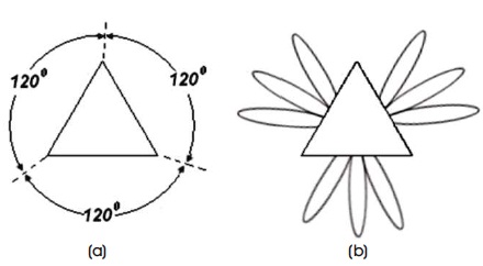
Figure 2. (a) Sectorized (b) Smart Antenna
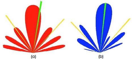
Figure 3. (a) Switched Beam System (b) Adaptive Array System
Mainly, there are two types of configurations, namely,
As smart antennas can focus their radiation pattern toward the desired user while rejecting all unwanted interference, they can provide a greater coverage area for each base station.
Most base stations can be modified to include smart antennas within each sector. This further subdivision enables the use of lower power level and provides for even higher system capabilities and greater bandwidths. With smart antenna the deleterious effects of multipath can be mitigated. Hence, dramatically fading in the received signal can be reduced.
A smart antenna reduces co-channel interference with multipath fading. Hence, higher data rates can be realized. Their direction findings capabilities also enhance geo-location services enabling a wireless system to better determine the location of a particular mobile user. It can direct the array main beam towards signals of interest even when no reference signal or training sequence is available. This capability is called blind adaptive beam forming.
Smart antennas also play a role in Multiple-Input and Multiple-Output (MIMO) communications systems. Since diverse waveforms are transmitted from each element in the transmit array and are combined at the receive array. Smart antennas will play a role in modifying radiation pattern in order to best capitalize on the presence of multipath. Smart antennas have a higher rejection of interference and therefore have a low Bit Error Rate (BER) (Yang & Shafai, 1994; Dakulagi & Bakhar, 2017a, 2017b; Bakhar & Vani, 2016; Bakhar, Vani, & Hunagund, 2014).
Another added advantage of smart antenna system is security. It makes it more difficult to tap a connection, because the intruder has to be positioned in the same direction as the user as seen from the base station to successfully tap a connection.
Finally, due to the spatial detection nature of smart antenna systems, they can be used to locate people in case of emergencies or for any other location specific services (Ghorbani & Waterhouse, 2004; Dakulagi, 2018; Dakulagi, Noubade, Agasgere, Doddi, & Fatima, 2019; Dakulagi & Bakhar, 2019; Veerendra, Bakhar & Vani, 2017)
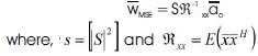
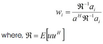
In the conventional beamformer, the weights are selected to be the conjugates of the steering vector i.e. for one path case the weights are selected as in equation (1) (Bakhar & Hunagund, 2009; Veerendra & Bakhar, 2016; Veerendra, Bakhar, & Vani, 2016).

where,
 -matrix of steering vectors
 -Cartesian basis vector
The main advantages of this method are its simplicity and it provides maximum output Signal to Noise Ratio (SNR) if the noise is uncorrelated and there are no directional jammers.
In this method optimizing the array weights is formed by minimizing the MSE. The optimized weight can be calculated as,
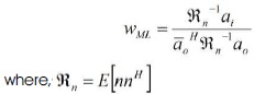
The Maximum Likelihood (ML) method is predicted on the assumption that it have an unknown desired signal x and s that unwanted signal n has a zero mean Gaussian distortion. The goal is to define a likelihood function which can give an estimate on the desired signal (Aspalli, Veerendra, & Hunagund, 2011).
This concept is based on minimizing the average output array power while marinating unity response in the look direction.
The problem can be describe mathematically as min H E[z(t)2] subject to wiHai = 1. The weights obtained by solving i i the above assumption problem will minimize the total noise. The MVDR beamformer maximizes the output signal to noise ratio. Lagrange multiplier method can be used to solve the problem and to get
The adaptive algorithm takes the fixed beamforming process one step further and allows for the calculation of continuously updated weights. The adaptation process must satisfy optimization criterion.
The least mean squares algorithm is a gradient based approach. The LMS solution is as follows
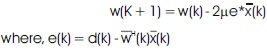
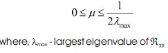
The convergence of the LMS algorithm is directly proportional to the step size parameter μ. Stability is insured provided that the following condition is met
This method is also known as Direct Matrix Inversion (DMI). This method circumvents the relatively slow convergence of the LMS scheme.
The SMI weights can be calculated for the kth block of length K as
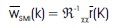
To demonstrate the performance of various adaptation techniques, computer simulation have been conducted using MATLAB. In these simulations, an N element arrays with spacing between elements d = 0.5λ are considered. The variance of σ2 = 0.001 is assumed. In each methods array element weights are calculated according to design equations given. Also, array factors are calculated o and plotted for the range -90 ≤ θ ≤ 90 . In all these methods the maximum signal strength is observed in θo desired direction with nulls in θ1 and θ2 interferers' directions.
Figures 4 - 9 shows the simulations results that shows the MSE beamformer has side lobe levels with large peaks. Meanwhile, the SMI beamformer has less amplitude side lobe levels.
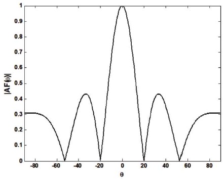
Figure 4. Array Pattern with N = 5, θo= 0o, θ1= -20o and θ2= 20o for Conventional Beamformer
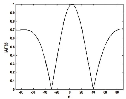
Figure 5. Array Pattern with N = 5, θo= 10o, θ1= -30o and θ2= 40o for MSE Beamformer
Figure 6. Array Pattern with N = 5, θo= 20o, θ1= -20o and θ2= 40o for Maximum Likelihood Beamformer
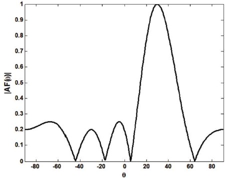
Figure 7. Array Pattern with N = 5, θo= 30o, for MVDR beamformer
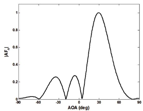
Figure 8. Array Pattern with N = 8, θo= 30o and θ1= -60o for LMS Beamformer
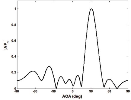
Figure 9. Array Pattern with N = 8, θo= 30o and θ1= -60o for SMI Beamformer
Hence, as compared to all the beamformers, SMI method has superior result in terms of beamwidth and peak side lobe levels.
Development of digital methods for antenna beam forming in the receiving mode of a radar can be advantageous in providing the system with a high degree of flexibility in beam-pattern management for countering Electronic Counter Measures (ECM) and providing multiple functions efficiently. The justification for incorporating digital methods and various possible arrangements are discussed first. The main body of this paper is a review of the mathematical basis for operating in the digital domain, and includes an analysis of the main causes of error so that a broad assessment of the precision of the method, compared with more conventional and better documented types, can be made (Dakulagi & Bakhar, 2017a).
The relationship between complexity of realisation with signal bandwidth, number of elements on one hand and number of simultaneous beams on the other, is also discussed. In this context, brief comments are made on anticipated advances in device technology. The function of controlling the beam-formation process is summarised from the point of view of allowing corrections to the weight values in real time to be made to compensate for errors in the antenna, its feeds and the multiple receiving channels, and providing an adaptive control of the beam patterns to optimise performance against jamming. The paper ends with a description of the operation of a small experimental digital beam former (Bakhar & Vani, 2016).
Present generation sonar systems employ high temporal and spatial resolution to achieve acceptable operational per formance. This, together with the physical mechanisms of acoustic propagation in the ocean, places a number of constraints on the implementation of beam-forming systems for sonar applications that are unique in many ways ; in particular:
This work outlines the impact of such factors on sonar beam-forming implementations and describes some of the techniques that have been developed, together with their practical realization using state-of-the-art digital LSI technology.
Smart Antennas have been gaining popularity in the recent times, as a means to enhance data rate. The reason behind this development is the availability of high-end processors to handle the complex computations involved. The major advantage of digital beamformer (smart antennas) is that phase shifting and array weighing can be performed on digital data rather than in hardware. This paper analyses the performance of three adaptive algorithms - Least Mean Square (LMS), Recursive Least Square (RLS) and Conjugate Gradient Method (CGM) for computing the array weights. In this paper, digital beamforming is also performed using Kalman based normalised Least Mean Square algorithm (Ghorbani & Waterhouse, 2004; Dakulagi, 2018).
This adaptive algorithm promises very high rate of convergence, highly reduced mean square error and low computational complexity compared to the existing adaptive algorithms. The weights obtained by the above algorithm are then used to steer the antenna array beam in the direction of interest, thereby enhancing SNR. One of the major requirements for Long Term Evolution (LTE), is high datarate, which can be achieved by smart antennas (Dakulagi et al., 2019; Dakulagi, & Bakhar, 2019).
Smart antenna is recognized as promising technologies for higher user capacity in 3G wireless networks by effectively reducing multipath and co-channel interference. Advent of powerful, low-cost, digital processing components and the development of software-based techniques has made smart antenna systems a practical reality for both base station and mobile station of a cellular communications systems in the next generation. The core of smart antenna is the selection of smart algorithms in adaptive array. Using beam forming algorithms the weight of antenna arrays can be adjusted to form certain amount of adaptive beam to track corresponding users automatically and at the same time to minimize interference arising from other users by introducing nulls in their directions. Thus, interferences can be suppressed and the desired signals can be extracted. This research work provides descriptive comparative analysis and utility of various reference signal based algorithms as well as blind adaptive algorithms. Exhaustive simulation study of beam patterns and learning characteristics have proved the efficacies of the proposed work from application point of view (Veerendra et al., 2016; Aspalli, Veerendra, & Hunagund, 2011).
The objective of this paper is to gives review of adaptive antennas with various types and benefits. Moreover, the different types of adaptation techniques used to form a beam in a particular desired direction with nulls in interferer directions in smart antenna systems are illustrated. Finally, computer simulations are done for four fixed weight and two adaptive beamformers. It has been shown that beam with maximum strength are formed in a desired direction with nulls in interferer directions.
It can be noticed that, from the results that the SMI beamformer has less beamwidth representing high directivity. Also, this method has less peak side lobe levels which conserves lot of power during the beamforming when used in any wireless technology. Hence the SMI algorithms outper forms as compared to other beamformers.